
Rpm, hub, blades: the Propeller tab prepares the propeller that the Heliciel designer computes in penstock mode.
Kaplan turbine runner: rpm, hub, blades and overlap
The runner is computed by Heliciel, with blade element theory in penstock mode. The Propeller tab sets its input data: rpm, hub, blade number and overlap, then sends it to the designer project.
Propeller tab of the left panel. Each block explained here carries a ? help icon in the window: clicking the icon opens the matching section of this page directly.
Contents:
- Runner rpm
- Runner hub diameter
- Blade number and overlap
- Sending the turbine to the Heliciel project and testing cavitation
Runner rpm

- Choose Similitude test rpm or Input.
- Read the blade flow angle.
- Run a solver again.
- Similitude test rpm: takes the rpm set in the Turbine type tab;
- Input (rpm).
Blade flow angle = Atan(axial velocity / blade tip speed), shown under the input.
In practice the rpm is imposed by the generator, its number of poles and any gearbox: choose it first, then vary the geometry.
Example
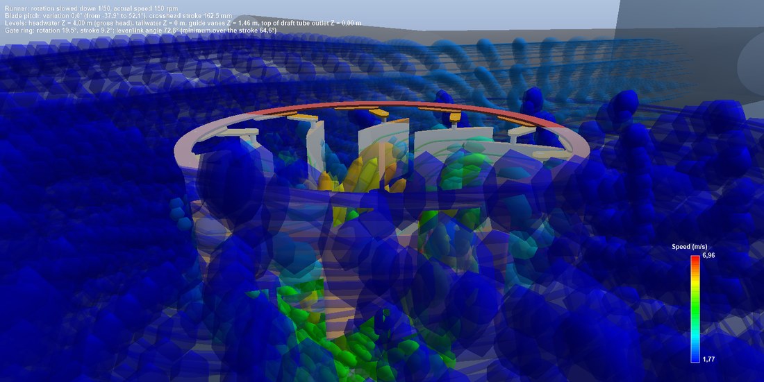
The runner rotating (slowed down on screen) and the water trajectories flowing through it.
Runner hub diameter
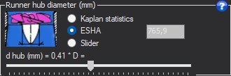
- Choose ESHA, Kaplan statistics or Slider.
- Check the hub in the dimensioned 3D cut.
- ESHA (Lugaresi and Massa): d = (0.25 + 0.0951 / NQe)·D;
- Kaplan statistics: ratio d/D1 of the similitude curve;
- Slider: blade root radius as a percentage of the radius.
The hub houses the pitch mechanism: too small, it no longer contains it; too large, it reduces the passage ring and accelerates the water.
Example
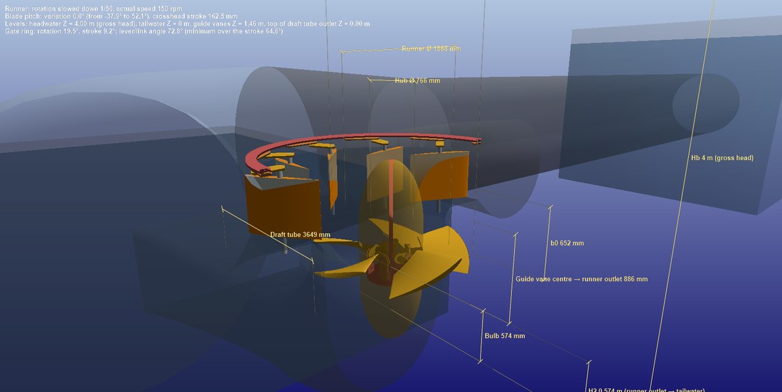
The runner in dimensioned cut: runner diameter and hub diameter.
Blade number and overlap
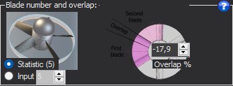
- Choose the blade number, input or statistic.
- Let the solver adjust the overlap, or set it by hand to study its effect on the absorbed head.
- Blade number: input, or statistic, the value proposed for the current specific speed being shown in brackets. The picture shows the matching runner.
- Overlap (%): overlap of the blades seen from the front. It changes the head absorbed by the runner without changing its rpm or its diameters: it is the variable the solvers adjust.
Example
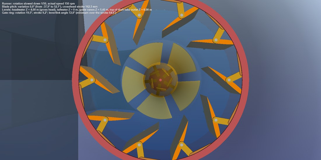
The runner seen from above: blade number and chord overlap.
Sending the turbine to the Heliciel project and testing cavitation
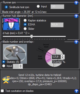
- Tick Test cavitation on blades if cavitation must be assessed.
- Click Send turbine data to Heliciel.
- Open the designer: the runner is rebuilt there in penstock mode.
The Send turbine data to Heliciel button rebuilds the propeller in the designer, in penstock mode, with:
- the available pressure ΔP = ρ·g·(Hb − path losses), used as the denominator of the penstock efficiency;
- the swirl produced by the distributor, sent as a solid-body rotation carrying the same angular momentum.
This button does not balance: if the runner and the path absorb more than the head, the project reports it. The draft tube is not transferred.
The Test cavitation on blades box sends an immersion depth equal to the gauge pressure at the runner inlet divided by ρ·g, so that the blade computation can detect cavitation. It is disabled during balancing and cavitation is judged afterwards.
In the project, the "exploited head ratio" compares only the static Δp of the runner with Hn; the share of head taken as swirl does not appear in it, but it is indeed converted into torque. The Method tab explains this balance.
Example
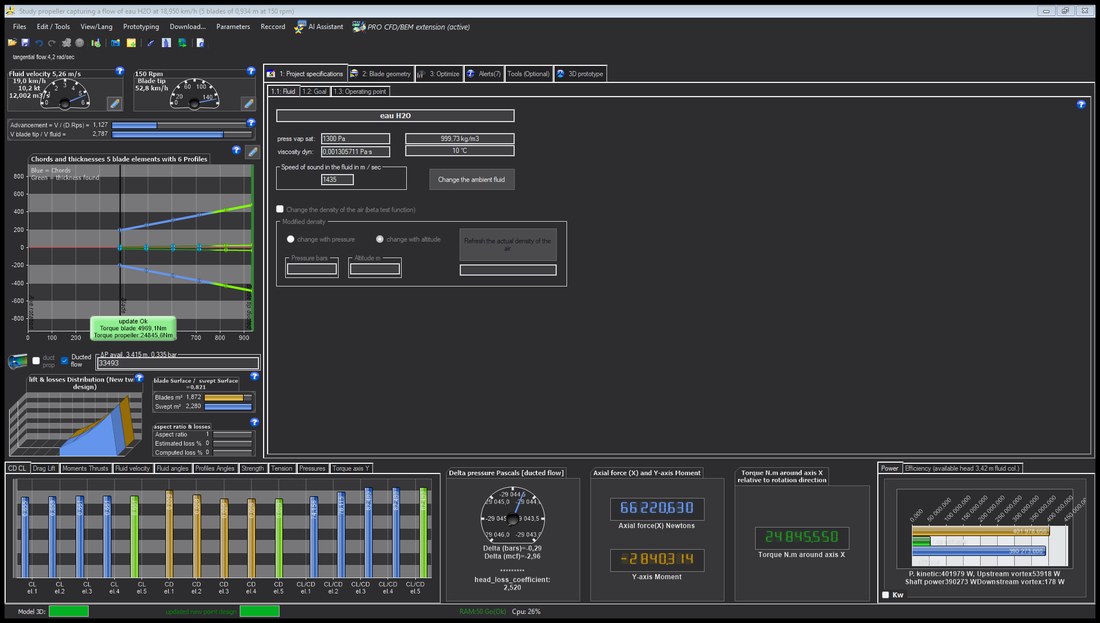
The Heliciel designer after sending: the project holds the turbine runner, in penstock mode, with its results. Its 3D view shows the runner alone.
Going further
The Hydro Turbine design reference page presents the complete method and a worked case. The other help pages of the window:
 Global site map
 Mecaflux
 Tutorials Mecaflux Pro3D
 Tutorials Heliciel
 Tutorials Heliciel PRO CFD
 Mecaflux Store
 Compare software functions
 Quotes, Orders, Payment Methods
 project technical studies