
Lift, drag, lift-to-drag ratio: three numbers, and the picture of the air that makes them.
Wing CFD: reading lift, drag and the pressure around the profile
Heliciel does not only do propellers, and neither does its CFD: a wing, a hydrofoil, a keel, a stabiliser are drawn and computed the same way. The designer gives lift and drag from the profile polar; the CFD (Computational Fluid Dynamics, numerical simulation of the flow) bench recomputes them on the whole wing, in three dimensions, and above all shows the air around the profile. This case study follows a wing in air; a hydrofoil is treated exactly the same way, only the fluid changes.
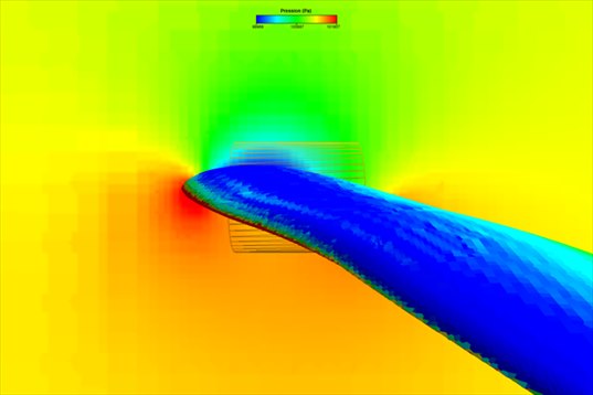
The picture every aerodynamics course draws by hand, computed here on the real wing: the red stagnation point at the leading edge, the green suction spreading over the top of the profile, the yellow-orange overpressure underneath. The difference between top and bottom is the lift.
- Contents:
- The wing and its flight point
- The wing in CFD at three mesh finenesses, three durations
- The pressure on the wing and around the profile
- The air accelerating over the upper surface
- And for a hydrofoil in CFD?
- Take-aways
1: The wing and its flight point
| Wing | wing model shipped with Heliciel, reference chord 1.90 m, reference area 8.6 m² (half-wing, the computation uses symmetry) |
| Speed | 52.35 m/s (188 km/h), air at 1.012 kg/m³ |
| Incidence | that of the project, already contained in the exported geometry |
| Reynolds number | 5.9 million, Mach 0.15: turbulent and incompressible flow |
2: The wing in CFD at three mesh finenesses, three durations
The same wing was computed with the three mesh presets offered for a wing. It is the only decision to take, and this table, drawn from the three runs, says what it buys:
| Preset | Cells | Meshing | Run | Lift CL | Drag CD | L/D |
|---|---|---|---|---|---|---|
| Fast (1/4) | 52,000 | 1 min 10 | 30 s | 0.886 | 0.0721 | 12.3 |
| Standard (2/4) | 198,000 | 3 min 23 | 1 min 11 | 0.901 | 0.0643 | 14.0 |
| Fine (3/4) | 811,000 | 28 min 30 | 5 min 09 | 0.906 | 0.0601 | 15.1 |
The reading is crystal clear: the lift hardly moves from one preset to the next (2 % between the first and the last), the drag drops at each step (−17 %), and the lift-to-drag ratio rises with it. A coarse mesh overestimates the drag: it does not describe finely enough the thin layer of slowed air sticking to the skin of the wing. For a lift, the fast preset is enough; for a drag or a lift-to-drag ratio, the fine preset is needed, and it counts in half-hours.
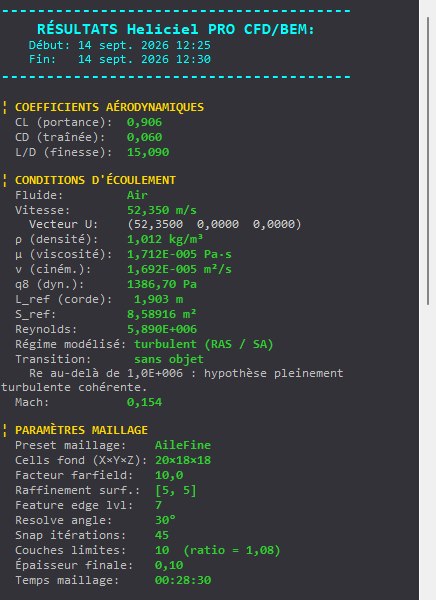
The results panel of the fine run: CL 0.906, CD 0.060, L/D 15.1, i.e. 10,795 N of lift for 715 N of drag. Below, the flow conditions and the recall of the preset used.
3: The pressure on the wing and around the profile
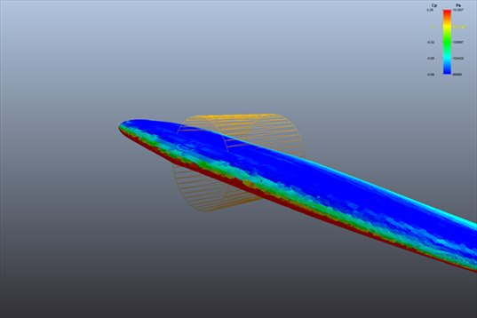
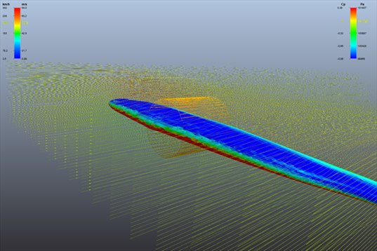
The top of the wing, seen in perspective from the tip. The whole upper surface is blue: in suction. The leading edge is red: this is where the air strikes. The orange wireframe cylinder is the bench's incidence zone marker, it is not part of the result.
The pressure cut at the top of the page completes this view: it shows that the suction does not stay stuck to the skin but extends into the air above the wing, over a thickness comparable to the chord. A wing lifts because it lowers the pressure of a large volume of air above it, not only at its surface.
4: The air accelerating over the upper surface
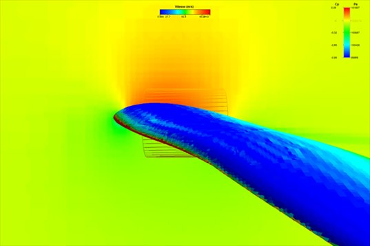
The same cut, coloured by velocity. The air arrives at 52 m/s (green). Above the wing it accelerates to more than 80 m/s (red): it is this acceleration that makes the suction of the previous picture. Under the wing, it hardly slows down.
The streamlines over the surface pressure: they follow the wing without separating. At this incidence, the flow is healthy over the whole span. A stall would show here as lines moving away from the skin and curling behind the trailing edge.
5: And for a hydrofoil in CFD?
Nothing changes in the approach. Heliciel ships a hydrofoil model; the fluid becomes water, about a thousand times denser than air, and the loads change scale: this is why a foil of a few square decimetres is enough to lift a boat. The CFD bench takes the fluid of the project, with its density, viscosity and vapour pressure, and the reading of the minimum pressure becomes, as for the boat propeller, the cavitation question: if the darkest blue of the upper surface drops below the vapour pressure, the foil cavitates.
6: Take-aways
- Lift is robust, drag is demanding: 2 % difference on lift between the fast and the fine mesh, 17 % on drag. Choose the preset according to the quantity sought.
- Three numbers and a picture: CL, CD, lift-to-drag ratio, and the pressure cut around the profile that shows where they come from.
- Stall can be seen on the streamlines before it can be read in the figures.
- A hydrofoil follows the same page, with cavitation to watch in addition on the pressure scale.
The CFD case studies
« Previous: Ducted fan CFD: duct and radiator
- Understanding a CFD result in five pictures
- Boat propeller CFD: thrust and pressure on the blades
- Aircraft propeller CFD: cruise and static thrust
- Drone propeller CFD: hover
- Wind turbine CFD: power and wake
- Tidal turbine CFD: a 16 m rotor in the current
- Ducted fan CFD: duct and radiator
- Wing CFD and hydrofoil: lift and drag (you are here)
These case studies complement the Heliciel design tutorials (in French), which cover the BEM side: blade design, choice of speed, performance curves. To go further into the method, the technical collection of twenty tutorials remains available.
 Global site map
 Mecaflux
 Tutorials Mecaflux Pro3D
 Tutorials Heliciel
 Mecaflux Store
 Compare software functions
 Quotes, Orders, Payment Methods
 project technical studies