
Toroidal propellers in Heliciel
The toroidal option joins the blades in pairs on a propeller designed by the blade element method. It applies to every type of propeller: aircraft, boat, drone, fan, wind and tidal turbine, from 4 to 8 blades.
The calculation brackets the toroidal propeller between two bounds, then the built-in CFD module places it between them.
Blade winglets in Heliciel
Ducted propellers: gain and limits
Blade tip losses
Toroidal propeller: how it works, advantages and disadvantages, compared with winglets and ducted propellers

RECURVED TOROID
PROPELLER DESIGN
Heliciel designs its own type of toroidal propeller: the Recurved Toroid. Seen from the front, each pair of blades joined at the tip draws a recurve bow: the blades leave the hub, spread apart, then their tips curve back towards each other and join.
The Recurved Toroid design function requires a Heliciel PRO licence: it does not appear in the other versions of the software. See the PRO CFD tutorials.
A toroidal propeller is a propeller whose blades are joined in pairs at their tips: each pair of neighbouring blades forms a closed loop with no free tip. By removing the blade tip, the toroidal propeller removes the concentrated vortex that forms there, and with it part of the tip losses. It is not better in every situation, though: its value depends on the number of blades, the operating point and the size of the loop, and it competes with two older solutions aimed at the same goal, winglets and the ducted propeller.
Heliciel offers a "toroidal propeller" option for every type of propeller: aircraft, boat, drone, fan, wind turbine and tidal turbine. This option is reserved for the Heliciel PRO licence. Every image on this page is a screenshot of Heliciel, and every figure is calculated by Heliciel on its project models. We varied the loop shape, the number of blades and the operating point, and compared each toroidal propeller with the same propeller with free tips, with winglets and with a duct.

Six-blade toroidal aircraft propeller (Ø 1.8 m) seen from the front in Heliciel: the six blades form three loops.
Contents:
- What is a toroidal propeller?
- Why join the blade tips: tip losses
- A toroidal propeller for every machine: aircraft, boat, drone, wind turbine, tidal turbine, fan
- Loop shapes of a toroidal propeller
- Comparative performance: toroidal propeller, winglets, ducted propeller
- Blade count, speed and loading: when is a toroidal propeller worthwhile?
- Advantages of the toroidal propeller
- Disadvantages and limits of the toroidal propeller
- Toroidal propeller or winglets?
- Toroidal propeller or ducted propeller?
- Joining the blade tips: the structural advantage
- Comparison table: toroidal, winglets, ducted
- Summary and analysis
- Designing a toroidal propeller with Heliciel
- 3D models of toroidal propellers
- Frequently asked questions about toroidal propellers
1: What is a toroidal propeller?
On a conventional propeller, each blade is a beam fixed to the hub and free at its tip. On a toroidal propeller, two neighbouring blades leave the hub, come closer to each other towards their tips, then meet through a curved junction. Together they draw a closed loop, hence the name taken from the torus. A four-blade toroidal propeller therefore has two loops, a six-blade propeller three loops, an eight-blade propeller four loops.
To bring the tips face to face, Heliciel shifts the two blades of a pair in opposite directions along their chord (an opposite skew), starting from a chosen radius. The junction then turns half a turn about the chord: the leading edge remains the leading edge all the way round, and the camber reverses progressively so that both blades push in the same direction. Halfway along, the section stands upright and its profile becomes symmetrical. This is the same distribution as on the closed wing (the "box wing") studied by Prandtl.
The idea was brought back into the spotlight by work on drone propellers (MIT Lincoln Laboratory), then by toroidal boat propellers sold for the leisure market. We do not reuse any figure from these sources: the performance shown on this page is the performance calculated by Heliciel.

The same toroidal propeller in three-quarter view: each loop leaves the hub and returns to it.
2: Why join the blade tips: tip losses
A blade produces thrust because the pressure on its working face is higher than on its back. At the blade tip, nothing separates the two faces: the fluid flows around the tip to equalise the pressures. Thrust therefore drops to zero at the tip, and this flow rolls up into a tip vortex that leaves in the wake, carrying energy away. This is the blade tip loss, which blade element calculation represents with Prandtl's factor.
Three solutions tackle this flow around the tip:
- the winglet folds the blade tip to hinder the flow around it and spread the vortex;
- the duct places a fixed wall all around the propeller, close to the blade tips: the fluid has almost no room left to flow around;
- the toroidal loop removes the free tip itself.
None of the three cancels the losses completely. A closed loop removes the concentrated vortex, but lift varies along the junction, which still sheds vorticity into the wake.
3: A toroidal propeller for every machine
Heliciel's toroidal option applies to any propeller or rotor with an even number of blades, from 4 to 8. Here, for each Heliciel project model, are the propeller with free tips and its toroidal version. Each propeller was recalculated at the model's operating point: twist and chords are optimised for the version studied.
Six-blade toroidal aircraft propeller

Ø 1.8 m, 1,000 rpm, 6 m/s in air, about 775 N of thrust.
Six-blade toroidal boat propeller


Ø 350 mm, 863 rpm, 3.86 m/s in sea water, about 1,800 N of thrust.
Four-blade toroidal drone propeller


Ø 127 mm, 25,000 rpm, hover, about 9.2 N of thrust.
Four-blade toroidal wind turbine
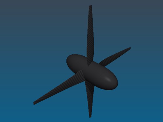
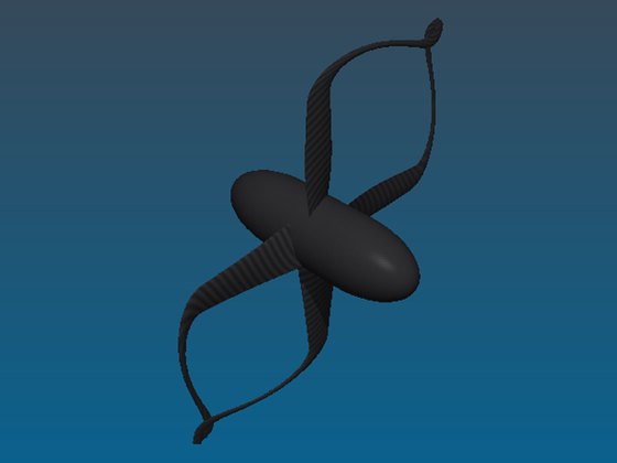
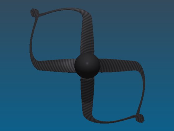
Ø 4 m, 167 rpm, 5.5 m/s wind, about 600 W. The blade tip of a wind turbine lies almost in the rotation plane: two neighbouring blades overlap there, and Heliciel refuses the loop if the deformation starts too close to the hub, because the blades would touch. Here it starts at 60 % of the radius, and the fold measures only 16.5 mm.
Four-blade toroidal tidal turbine
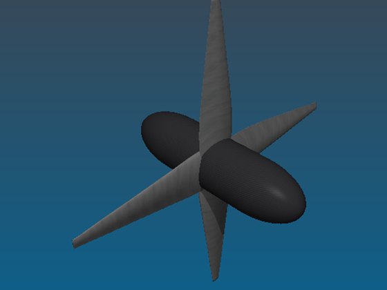
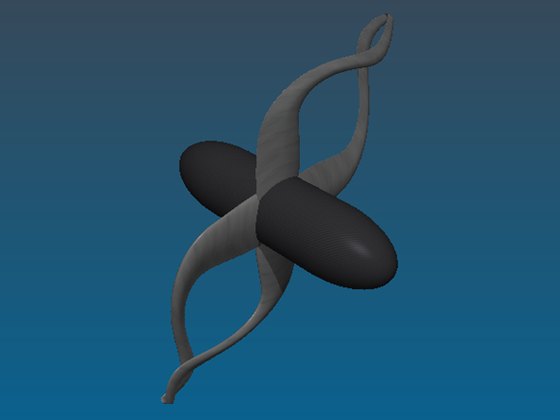

Ø 16 m, 18.2 rpm, 2.4 m/s current, about 360 kW.
Eight-blade toroidal fan


Ø 1.25 m, 960 rpm, 13.6 m/s, about 560 N, without a conduit.
4: Loop shapes of a toroidal propeller
The loop shape is set in a dedicated window: junction height (from semicircle to square junction), closing of the tips by an opposite rake of the two blades, radius where the deformation starts, steepness of the transition, apex chord and departure angle of the junction. Eight presets cover the common shapes. Here are all eight on the same six-blade aircraft propeller.

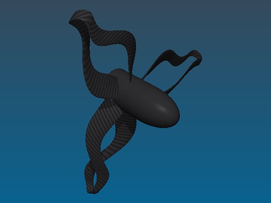
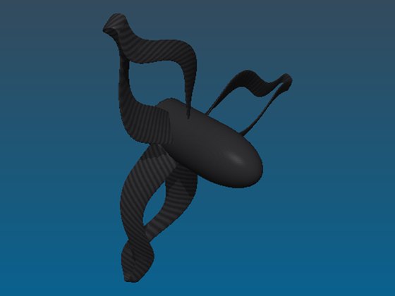
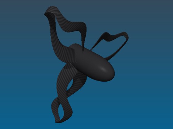
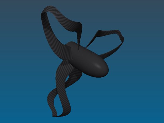

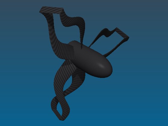
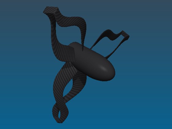
Seen from the side, the loops show their extent along the axis:

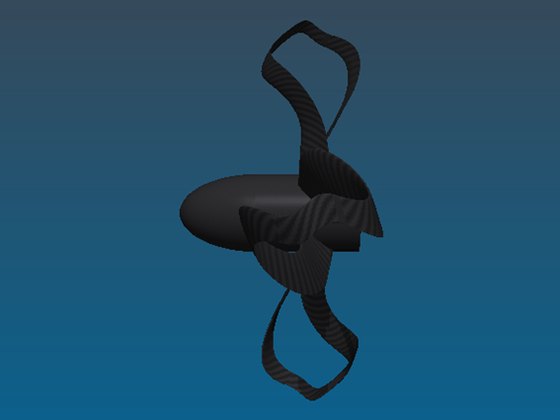
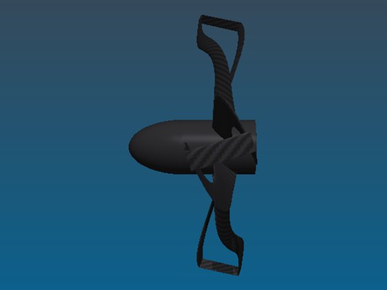
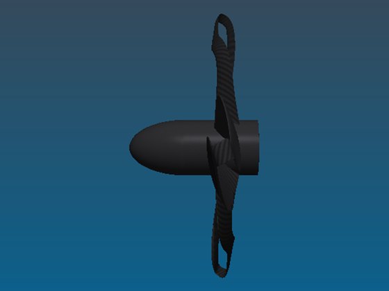
The loop shape matters: on the aircraft propeller, the area of one junction drops from 341 cm² (round loop) to 95 cm² (very compact loop), and the thrust-to-power ratio (upper bound) rises from 53.1 to 54.4 N/kW. The more compact the loop, the less its drag costs. On the drone, the large round loop even loses 3 % against free tips: it is too big next to 6 cm blades.

Heliciel's "Toroidal propeller" window (shown here in the French interface): settings, derived quantities, junction sketch and axial view of the blade pair (blade A in blue, junction in orange, blade B in green).
5: Comparative performance: toroidal propeller, winglets, ducted propeller
For each machine, we compare four versions recalculated at the same operating point (same speed of rotation, same flow speed): free tips, winglets (height 10 % of the radius), toroidal propeller and ducted propeller. The quantity compared is the thrust-to-power ratio for propulsive propellers, and the power produced for wind and tidal turbines.
For the toroidal propeller, Heliciel gives two bounds: the upper bound assumes tip losses are removed entirely, the lower bound keeps the tip losses of the free-tipped blades. Both include the drag of the junctions. The real loop lies between the two, and only a CFD calculation can say where. Heliciel's ducted mode makes the same assumption as the upper bound (tip losses removed) without counting the drag of the duct; it is therefore an upper estimate as well.
| Machine (quantity compared) | Free tips | Winglets | Toroidal, upper bound | Toroidal, lower bound | Ducted |
|---|---|---|---|---|---|
| Aircraft, 6 blades (N/kW) | 53.5 | 53.8 (+0.6 %) | 54.4 (+1.6 %) | 53.2 (−0.5 %) | 54.9 (+2.6 %) |
| Boat, 6 blades (N/kW) | 143.9 | 146.4 (+1.8 %) | 151.6 (+5.4 %) | 145.4 (+1.1 %) | 153.1 (+6.4 %) |
| Drone, 4 blades, hover (N/kW) | 42.3 | 42.3 (+0.1 %) | 42.4 (+0.2 %) | 41.6 (−1.6 %) | 43.2 (+2.2 %) |
| Fan, 8 blades (N/kW) | 35.3 | — | 37.2 (+5.6 %) | 35.8 (+1.6 %) | 37.5 (+6.4 %) |
| Wind turbine, 4 blades (W produced) | 600 | — | 618 (+2.9 %) | 598 (−0.4 %) | 617 (+2.8 %) |
| Tidal turbine, 4 blades (kW produced) | 357.6 | — | 369.6 (+3.3 %) | 355.9 (−0.5 %) | 371.4 (+3.8 %) |
Loop shapes used: very compact (aircraft, boat, drone), tapered (fan, tidal turbine), round with deformation from 60 % of the radius (wind turbine). Winglets were calculated on the three propulsive propellers only.


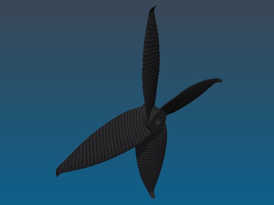
The four versions of the six-blade boat propeller compared in the table.




6: Blade count, speed and loading: when is a toroidal propeller worthwhile?
Tip losses do not weigh equally on every propeller. They are larger when the blades are few and when the wake rolls up into a helix of large pitch: the fluid then has more room to flow around the tips. To measure this, we took the aircraft propeller with 4, 6 and 8 blades and recalculated it at four advance speeds, from static thrust to 40 m/s, with free tips and as a very compact toroidal propeller.
| Blades | Advance speed | Advance ratio J | Toroidal, upper bound | Toroidal, lower bound |
|---|---|---|---|---|
| 4 | 0 / 6 / 20 / 40 m/s | 0 / 0.20 / 0.67 / 1.33 | +1.8 / +2.5 / +2.5 / +1.7 % | −0.9 / −0.5 / −0.3 / −0.7 % |
| 6 | 0 / 6 / 20 / 40 m/s | 0 / 0.20 / 0.67 / 1.33 | +1.2 / +1.8 / +2.0 / +1.7 % | −0.6 / −0.4 / −0.2 / −0.3 % |
| 8 | 0 / 6 / 20 / 40 m/s | 0 / 0.20 / 0.67 / 1.33 | +0.9 / +1.3 / +1.7 / +1.6 % | −0.5 / −0.4 / −0.2 / −0.2 % |
Change in thrust-to-power ratio against the same propeller with free tips, recalculated at the same point. Aircraft propeller Ø 1.8 m, 1,000 rpm.
Three lessons:
- The fewer the blades, the more the loop can gain: at 6 m/s, the upper bound is +2.5 % with 4 blades and +1.3 % with 8 blades.
- Static thrust is not the most favourable case here: the gain is smaller at static thrust than at medium speeds, because the wake pitch is smaller and tip losses count for less. The rule "the more heavily loaded the propeller, the more useful the loop" holds when loading increases the wake pitch: this is the case of slow, heavily loaded propellers such as the boat propeller (+5.4 %), not of a fast drone rotor in hover (+0.2 %).
- The drag of the junctions is always there: the lower bound, which keeps the tip losses, is 0.2 to 0.9 % below free tips. If the real loop removes tip losses poorly, the toroidal propeller loses a little efficiency.
7: Advantages of the toroidal propeller
- Lower tip losses: the concentrated vortex disappears. In our calculations, the upper bound gains 0.2 to 5.6 % depending on the machine.
- No duct to carry: the gain comes without a fixed duct, hence without its weight, its own drag and its supports.
- No tip clearance to hold: a ducted propeller loses its advantage as soon as the gap between the blades and the wall grows; the toroidal loop has no such tolerance constraint.
- A stiffer structure: the blades are no longer beams free at their tip (see the structure section).
- Less noise, according to published drone studies: the tip vortex is a noise source. This is the main argument put forward for toroidal drone propellers. Heliciel does not quantify it for this geometry.
- Less tip vortex cavitation in marine use (assumption): on a boat propeller, the core of the tip vortex is often the first place to cavitate. Removing the concentrated vortex should delay this form of cavitation; this is an expectation, to be checked by CFD calculation.
8: Disadvantages and limits of the toroidal propeller
- A larger wetted area: the junction adds friction drag and mass at the largest radius. On the aircraft propeller, a round loop adds 341 cm² per junction, three times more than a very compact loop.
- Difficult manufacturing: the loop is a continuous warped surface joining two blades with different pitch and twist. It is made by casting, 3D printing or five-axis machining. Heliciel exports it as STL, OBJ and GLB, but not as STEP or IGES.
- No variable pitch: rotating the blades would open the loops. A toroidal propeller is a fixed-pitch propeller.
- An even number of blades: the blades come in pairs, from 4 to 8 in Heliciel.
- Neighbouring blades that must not touch: when the blade tip lies almost in the rotation plane, as on a wind turbine, the blades of a pair cross if the deformation starts too early. Heliciel then refuses the shape and states at which radius the blades touch.
- A statically indeterminate structure: the closed frame can no longer be calculated as a cantilever beam. Heliciel flags this with a warning.
- A larger overall size: the loop extends beyond the blade radius (overall diameter of 1,873 mm for the 1,800 mm aircraft propeller with very compact loops).
9: Toroidal propeller or winglets?
Geometrically, a toroidal loop is the limit of two winglets that meet: each winglet folds the blade tip by about a quarter turn about its chord, and the loop chains two such folds up to the neighbouring blade.
- Effectiveness: in our calculations, winglets of 10 % of the radius gain +0.6 % (aircraft), +1.8 % (boat) and +0.1 % (drone). The upper bound of the toroidal propeller goes further (+1.6, +5.4 and +0.2 %), but its lower bound is below the winglets.
- Added surface: a winglet adds little surface; the toroidal junction adds more.
- Manufacturing: a blade with a winglet remains an independent blade; the loop ties two blades together.
- Structure: the winglet leaves the blade cantilevered and adds mass at the tip; the loop turns it into a frame.
- Compatibility: the winglet works with an odd number of blades and with variable pitch; the toroidal propeller does not.
10: Toroidal propeller or ducted propeller?
The ducted propeller also achieves a large reduction in tip vortex losses, by other means: the fixed wall prevents the flow around the tip. It has a decisive practical advantage over the toroidal propeller: it is simpler to manufacture. The blades remain conventional, independent blades, and the duct is a body of revolution that can be turned, rolled or moulded without difficulty.
In our calculations, the ducted propeller always matches the upper bound of the toroidal propeller, or does slightly better (+2.6 against +1.6 % on the aircraft, +6.4 against +5.4 % on the boat). The difference is mainly the drag of the junctions, which the toroidal calculation counts. Note that the ducted calculation does not count the drag of the duct, nor its own thrust at high loading.
- Tip losses: with a small clearance, the duct reduces them strongly. The toroidal loop reduces them with no clearance to hold.
- Duct thrust: at high loading, the inlet lip of a well-shaped duct produces thrust of its own. The toroidal propeller has no such effect, but it does not carry the drag of the duct either, which penalises the duct at high speed.
- Weight and size: the duct and its supports add weight and bulk; the loop only adds the mass of its junctions.
- Protection: the duct protects the blades and their surroundings; the toroidal propeller remains an open propeller.
- Variable pitch: compatible with a ducted propeller, impossible on a toroidal propeller.
Heliciel distinguishes two ducted arrangements, the ducted propeller in free stream and the propeller in a closed conduit: see free stream, ducted propeller and closed conduit. The toroidal option is compatible with neither.
11: Joining the blade tips: the structural advantage
A conventional blade is a cantilever beam: thrust bends it, centrifugal force pulls on it, and its tip vibrates freely. On a toroidal propeller, each loop connects two blades: the tip is no longer free, and the closed frame bends less and vibrates less. This is a real advantage for long, slender blades.
This advantage is not unique to the toroidal propeller. It also exists in ducted propellers whose blades are fixed to a rotating ring: ring propellers, or rim-driven thrusters, where the motor rim carries the blades by their tips. In a ducted propeller with a fixed nozzle, on the other hand, a clearance separates the blades from the wall: the blades remain cantilevered.
The price is the same for the ring and for the loop: the structure becomes statically indeterminate, and stresses concentrate at the joints. The sizing of a cantilever blade as Heliciel performs it (blade strength) no longer applies as such: Heliciel shows the junction mass (0.26 kg per loop on the carbon aircraft propeller with very compact loops) and warns that the closed frame is not calculated for strength.
12: Comparison table: toroidal propeller, winglets, ducted propeller
| Criterion | Toroidal propeller | Winglets | Ducted propeller |
|---|---|---|---|
| Gain calculated by Heliciel (6 machines) | Upper bound +0.2 to +5.6 %; lower bound −1.6 to +1.6 % | +0.1 to +1.8 % (3 propulsive propellers) | +2.2 to +6.4 % (without duct drag) |
| Reduction of tip losses | Strong (no free tip) | Partial | Strong if the clearance is small |
| Added wetted area | Medium (junctions) | Small | Large (duct) |
| Thrust of the device itself | No | No | Yes, at high loading |
| Manufacturing | Difficult (continuous warped loop) | Fairly simple | Simple (conventional blades + body of revolution) |
| Blade stiffness | Increased (closed frame) | Unchanged, mass at the tip | Increased only if the blades are fixed to a rotating ring |
| Variable pitch | Impossible | Possible | Possible |
| Number of blades | Even (4, 6, 8) | Any | Any |
| Blade protection | No | No | Yes |
13: Summary and analysis
- The toroidal propeller gains mostly where tip losses are large: slow, loaded propeller (boat, +5.4 % upper bound), fan without conduit (+5.6 %), turbines (+2.9 to +3.3 %), few blades. On a fast drone rotor in hover or an eight-blade propeller, the possible gain is small.
- The loop must stay compact: on a small propeller, a large loop costs more in drag than it brings.
- Against winglets, the toroidal upper bound is better, the lower bound worse: the advantage depends on the real effectiveness of the loop, which only CFD can settle.
- Against the ducted propeller, the toroidal propeller reaches at best the same order of gain, without a duct or a clearance to hold, but with harder manufacturing and no variable pitch. The duct remains the simple choice when its size, weight and drag are acceptable.
- These figures are model results: the interaction between the two legs of a loop and the vorticity shed by the junction are not represented by blade element calculation. Heliciel's CFD bench is used to place each toroidal propeller between its two bounds.
14: Designing a toroidal propeller with Heliciel

Heliciel (French interface) with the six-blade toroidal aircraft propeller: the "Toroidal" check box sits next to "Duct" and "Penstock".
Designing toroidal propellers requires a Heliciel PRO licence. In the other versions of Heliciel, the "Toroidal" check box and its settings window do not appear.
The option starts from a propeller designed in the usual way by the blade element method, then joins its blades in pairs:
- a "Toroidal" check box, next to the duct and closed conduit options, with which it is incompatible; it also removes the winglet and the rounded tip;
- a settings window with eight presets and the fine settings of the loop. Heliciel derives from them the fold diameter, the skew difference that closes the loop, the overall diameter, and the length, area and mass of the junction;
- a complete 3D geometry, visible in the 3D view, exportable as STL, OBJ and GLB for 3D printing, and usable by the CFD module, whose rotating zone is enlarged to the loop;
- a bracketed calculation: upper bound without tip losses, lower bound with the tip losses of the free-tipped blades, junction drag and mass counted, without any hand-tuned intermediate coefficient.
The built-in CFD calculation then places the real toroidal propeller between these two bounds. This two-step approach is the one Heliciel already applies to winglets and ducts.
15: 3D models of toroidal propellers
Print-ready 3D models of toroidal propellers will be offered on this page. Meanwhile, all the 3D propeller models of the shop are available.
16: Frequently asked questions about toroidal propellers
Is a toroidal propeller more efficient than a conventional propeller?
Not always. In Heliciel's calculations, its upper bound gains 0.2 to 5.6 % depending on the machine, but its lower bound, which keeps the tip losses, is up to 1.6 % below free tips because of the drag of the junctions. The gain is clearest on slow, loaded propellers with few blades.
Why would a toroidal propeller be quieter?
Because the tip vortex, which it partly removes, is a noise source. This is the main argument put forward for toroidal drone propellers.
What is the difference between a toroidal propeller and a ducted propeller?
The ducted propeller reduces tip losses with a fixed duct around the blades, which is simpler to manufacture and produces thrust of its own at high loading. The toroidal propeller reduces them by joining the blades together, without a duct, but at the cost of harder manufacturing.
Is a toroidal propeller better than winglets?
Its upper bound is (+5.4 % against +1.8 % on the boat propeller calculated by Heliciel), its lower bound is not. The real advantage depends on the effectiveness of the loop, to be checked by CFD calculation.
Can a toroidal propeller have variable pitch?
No: rotating the blades would open the loops that join them. A toroidal propeller is fixed-pitch.
How many blades does a toroidal propeller have?
An even number, since the blades are joined in pairs: 4, 6 or 8 in Heliciel. The fewer the blades, the more the loop can gain.
How is a toroidal propeller manufactured?
By casting, 3D printing or five-axis machining: the loop is a continuous surface that cannot be split into simple parts. Heliciel exports the geometry as STL, OBJ and GLB.
Which Heliciel licence do I need to design a toroidal propeller?
A Heliciel PRO licence. The toroidal option (Recurved Toroid model) does not appear in the other versions of the software.
 Global site map
 Mecaflux
 Tutorials Mecaflux Pro3D
 Tutorials Heliciel
 Tutorials Heliciel PRO CFD
 Mecaflux Store
 Compare software functions
 Quotes, Orders, Payment Methods
 project technical studies