
Chord distribution of blades and wings: how to lay it out?
The chord distribution of blades and wings is the width of the profiles along the blade or wing: it decides where the lift concentrates, and therefore how large the tip losses are. For a wing, the best shape is the ellipse. For a propeller, the profiles near the shaft must be widened, because they see a slower flow than those at the blade tip.
In this article:
- Blade dimensions: shaping the blade with sliders
- Blade tip losses: why the lift distribution matters
- Apparent velocity and lift of a propeller or wind turbine blade
- Lift distribution: propeller blade or wing
- Elliptical lift: which chord distribution to choose?
- Blade chord and cavitation
1: Blade dimensions: shaping the blade with sliders
The distribution of the profile chords defines the geometry of the blades of a wind turbine, a tidal turbine, a boat propeller, an aircraft propeller or a fan. It is one of the factors that weigh most on blade performance.
In the blade dimensions tab, a series of sliders lets you shape the blade or wing: chord at the root, chord at the tip, intermediate chords, root radius and diameter. You impose these values; Heliciel derives the area, the aspect ratio and the tip losses from them.
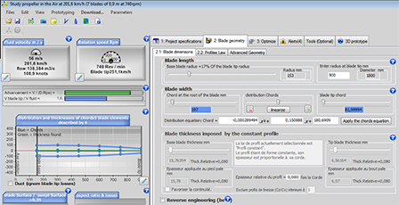
The blade dimensions tab: chord sliders, root radius and diameter. The graph on the left redraws the blade at every adjustment.
2: Blade tip losses: why the lift distribution matters
We saw with wings that at a wing tip the fluid flows around the profile, from the pressure side to the suction side. These leaks cost lift and create induced drag, which lowers the efficiency and the lift-to-drag ratio. The page on wing and blade tip losses describes the phenomenon in detail.
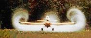
Wing tip vortices, made visible by dust or mist.
A propeller or wind turbine blade is a rotating wing: it suffers the same losses, and the shape of the blade must account for them. These losses grow as the aspect ratio falls. A helicopter blade is so long and narrow that its tip losses stay very small.
We are often limited in length, however. What remains is to distribute the chords so that the lift concentrates as far as possible from the tips. For a wing, the shape that best meets this condition is the ellipse, as we said in the article on wings.
3: Apparent velocity and lift of a propeller or wind turbine blade
On a rotating wing such as a propeller blade, each blade element sees two combined velocities: the rotational velocity (Ω × r, with Ω the angular velocity and r the radius of the element) and the velocity of the fluid upstream of the propeller. Their resultant is the apparent velocity.
The rotational velocity grows with the radius. An element at the blade tip therefore sees a higher velocity than an element near the shaft. At mid-radius, for example, the velocity due to rotation is half that at the tip.
This matters a great deal, because lift depends on the square of that velocity:
The formula for lift (2D):
Lift (N) = Cl × S × ρ × V² / 2
with Cl the lift coefficient of the profile, S the area of the wing or element (m²), ρ the fluid density (kg/m³) and V the velocity seen by the profile (m/s).
Ignoring tip losses, lift therefore varies with the square of the velocity. With equal chords, a rotating wing concentrates its lift on the fastest elements, that is, towards the tip. At mid-radius, and when rotation dominates the forward speed, an element of the same area carries about four times less lift than at the tip.
4: Lift distribution: propeller blade or wing
Heliciel updates the chord distribution diagram, and the lift distribution that follows from it, at every change of geometry. The two graphs below show the same shape, applied first to a propeller blade, then to a wing.
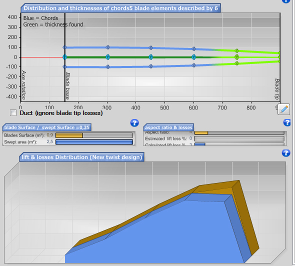
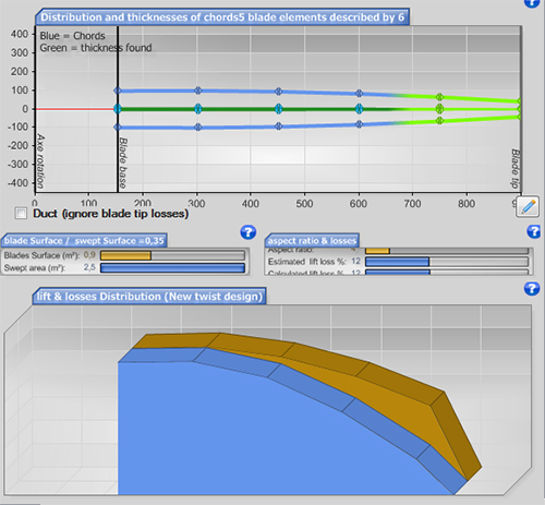
Chords (top) and lift (bottom) on 5 elements, for a propeller (first image) and for a wing of the same developed shape (second image). The propeller lift concentrates towards the tip; the wing lift follows the chord.
Velocity explains the difference. On the blade, the relative velocity is higher at the tip, so the lift is stronger there. On the wing, the relative velocity is constant, so the lift follows the chord distribution.
5: Elliptical lift: which chord distribution to choose?
The best lift distribution is elliptical. For a wing, that corresponds to an elliptical chord distribution. For a propeller, you must increase the chords of the elements near the shaft, to compensate for the lower velocity they see.
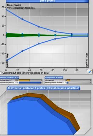
A chord distribution wide near the shaft and narrow at the tip: the lift spreads over the blade and moves away from the tip, so the losses fall.
Here side by side are a commercial wind turbine, whose blades have a wide chord near the hub, and an elliptical wing, that of the Spitfire. Both shapes aim at the same effect: keeping the lift away from the tips.
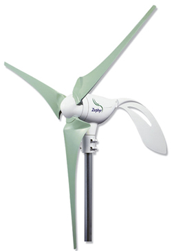
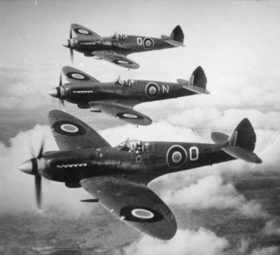
Left, a commercial wind turbine with tapered blades; right, Spitfires and their elliptical wings.
So distribute your chords to cut the blade tip losses as far as possible, and gain efficiency. For a propulsive propeller, the notion of efficiency needs a precision: we then speak of propulsive efficiency.
6: Blade chord and cavitation
The chord sets the blade area on which the lift force acts. For propellers and hydrofoils in liquid, it therefore affects the conditions in which cavitation forms: for the same lift, a wider chord spreads the load over a larger area.
To go further, we can look at propeller and wind turbine blades, or at how the blade tip loss is calculated.
 Global site map
 Mecaflux
 Tutorials Mecaflux Pro3D
 Tutorials Heliciel
 Tutorials Heliciel PRO CFD
 Mecaflux Store
 Compare software functions
 Quotes, Orders, Payment Methods
 project technical studies