
The spiral casing spreads the water all around the distributor at constant velocity. Its inlet diameter is chosen from the material.
Turbine spiral casing: inlet diameter and water velocity
The spiral casing, or volute, brings the water from the penstock all around the distributor. It narrows as it gives water to the guide vanes, to keep a constant velocity. The Spiral casing tab sets whether it exists, its inlet diameter and the flow direction it gives to the distributor.
Spiral casing tab of the left panel. Each block explained here carries a ? help icon in the window: clicking the icon opens the matching section of this page directly.
Contents:
- With or without casing: flow direction at the distributor inlet
- Casing inlet diameter and water velocity
- Recommended casing velocity by material
With or without casing: flow direction at the distributor inlet

- Choose Inlet from casing or No casing.
- Read the computed inlet direction.
- Check in the top view that the guide vanes are aligned with this flow.
- Inlet from casing: the water enters the distributor with a tangential component, that of the casing. Inlet direction = Atan(Vr inlet / Ve casing), Vr being the radial velocity at the distributor inlet and Ve the velocity in the casing.
- No casing: the water arrives radially, inlet direction = 90°.
The resulting angle feeds the "inlet angle of attack" loss of the distributor: guide vanes badly oriented with respect to this flow create a shock loss.
Example
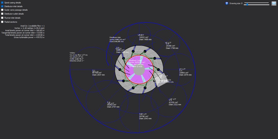
Top view with casing and distributor inlet details: the flow direction at the guide vane inlet.
Casing inlet diameter and water velocity
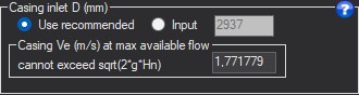
- Choose Use recommended, or Input and type the diameter.
- Read the inlet velocity Ve.
- Read in the table the sections S1 to S8 that keep this velocity along the spiral.
- Use recommended: the diameter follows from the allowable velocity of the material chosen in the Recommended speed block.
- Input: you impose the inlet diameter (mm).
- Casing Ve: inlet velocity at maximum flow, derived from the diameter. It cannot exceed √(2·g·Hn).
The casing narrows along its path, in eight sections S1 to S8 shown in the table of the tab, as it gives water to the distributor: it thus keeps this velocity constant.
Examples
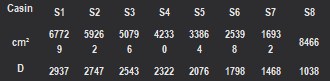
The table of the eight casing sections, S1 to S8: decreasing areas and diameters.
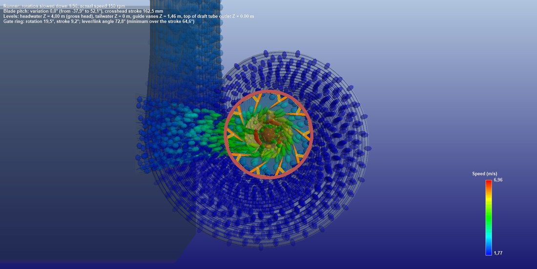
The casing seen from above in 3D: the water velocity stays roughly constant along the spiral.
Recommended casing velocity by material
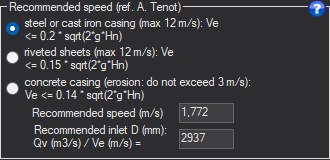
- Tick the casing material.
- Read the recommended velocity and the matching inlet diameter.
- Go back to the inlet diameter block and choose "Use recommended" to apply it.
Three rules, from the A. Tenot reference, are chosen by radio button:
- steel or cast iron casing: Ve ≤ 0.2·√(2·g·Hn), capped at 12 m/s;
- riveted sheets: Ve ≤ 0.15·√(2·g·Hn), capped at 12 m/s;
- concrete: Ve ≤ 0.14·√(2·g·Hn), not exceeding 3 m/s because of erosion.
The block shows the recommended velocity and the matching inlet diameter, which the Casing inlet D block applies when "Use recommended" is selected.
Example
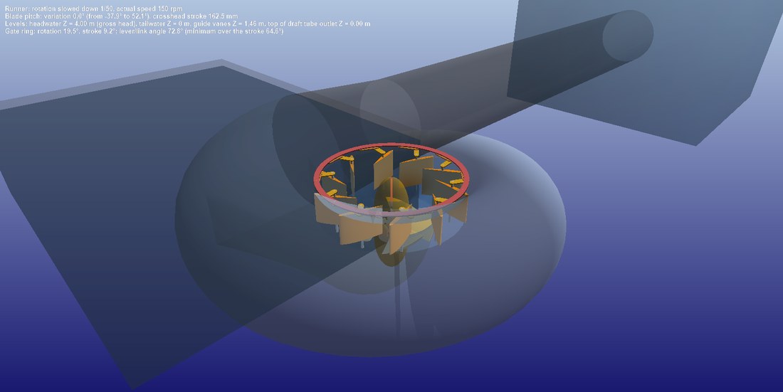
The spiral casing in 3D: its inlet diameter follows from the velocity allowed by the material.
Going further
The Hydro Turbine design reference page presents the complete method and a worked case. The other help pages of the window:
 Global site map
 Mecaflux
 Tutorials Mecaflux Pro3D
 Tutorials Heliciel
 Tutorials Heliciel PRO CFD
 Mecaflux Store
 Compare software functions
 Quotes, Orders, Payment Methods
 project technical studies