
Water is 900 times denser than air: the loads change scale, the method does not.
Tidal turbine CFD: 45 tonnes of thrust in a tidal current
A tidal turbine in CFD is a wind turbine under water. The tidal current is slow, 2 to 3 m/s, but sea water weighs 900 times more than air: a 16 m rotor undergoes loads of several tens of tonnes. This case study repeats the approach of the wind turbine case on a large marine machine, and shows that the CFD (Computational Fluid Dynamics, numerical simulation of the flow) bench changes neither its method nor its duration when the machine goes from 4 m to 16 m and from air to water.
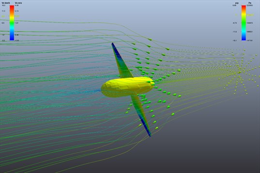
The 16 m two-blade rotor in its current. The streamlines, yellow upstream, turn green-blue as they cross the rotor: the water has slowed down. The blade tips are dark blue, where the suction is strongest.
- Contents:
- The machine and the current
- The tidal turbine loads in CFD: 45 tonnes
- The tidal turbine wake in the current
- What CFD confirms, and what it does not
- Take-aways
1: The machine and the current
| Rotor | 2 blades, diameter 16 m, hub ∅ 2.72 m, mean chord 1.67 m |
| Current | 2.4 m/s (4.7 knots), sea water at 1,028 kg/m³ |
| Speed | 18.2 rpm, i.e. 15.2 m/s at the blade tip |
| Shaft immersion | 10 m |
| Heliciel designer (BEM) | 631,600 N of thrust on the rotor, 409,200 N·m of torque |
The Level 5 mesh took 5 minutes for 148,000 cells: no more than for the 1.14 m boat propeller. The bench fits the domain and the cell size to the machine; a 16 m rotor costs no more than a 1 m one. The first phase of the computation (frozen rotor) took 2 min 12; the second (really rotating rotor) 1 h 38, to simulate 1.1 revolution of this slow rotor.
2: The tidal turbine loads in CFD: 45 tonnes
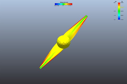
The rotor seen facing the current. The exposed face is yellow-red: the water presses on the whole blade, with a maximum along the leading edge. It is this pressure, on two 6.6 m blades, that makes the 45 tonnes of thrust.
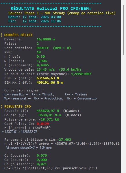
The results panel after the first phase: 433,700 N of thrust on the blades, about 44 tonnes. The designer's reference is recalled above: 631,600 N. The torque of this first phase is to be ignored, we come back to it below.
| Thrust on the rotor | Torque | |
|---|---|---|
| Heliciel designer (BEM) | 631,600 N | 409,200 N·m |
| CFD, frozen rotor | 450,700 N (−31 %) | not usable |
| CFD, rotating rotor | 476,600 N (−27 %) | 170,500 N·m (−58 %) |
The order of magnitude is there: 45 to 48 tonnes of axial thrust on the structure carrying the rotor, a little less than the designer's 63 tonnes. To size the mast, the base or the mooring of a tidal turbine, these are the figures to keep, with the highest as an envelope. The fluctuation computed in real rotation, 10,000 N, is only 2 % of it: a slow two-blade rotor in a uniform current is a regular machine.
3: The tidal turbine wake in the current
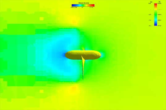
Vertical velocity cut, seen from the side. The current arrives from the right in green (2.4 m/s). Behind the rotor, the blue zone is the slowed water whose energy has been taken; it extends over several diameters. A neighbouring tidal turbine placed in that zone would produce less: this is the spacing question in a farm.
The same picture as for the wind turbine, and for the same reason: a machine that captures the energy of a fluid necessarily slows it down. The wake, invisible at sea, is here measurable point by point: the probe of the CFD bench gives the velocity at any point clicked on the cut.
4: What CFD confirms, and what it does not
The CFD bench accompanies its results with alerts. On this case, they say in plain words:
- "The thrust (Fx) is reliable": it is a load integrated over the whole blade surface, robust to the mesh. Frozen or rotating rotor, we find 45 to 48 tonnes again.
- The torque requires "resolving the circulation around the blade profiles", which a 148,000-cell mesh does not do on 6.6 m blades. With the frozen rotor, the torque even comes out with the wrong sign: the lift and the friction of the blades almost cancel out, and the small difference is poorly computed. The real rotation puts it right (170,500 N·m, the right sign) but stays at −58 % of the designer.
- The fluctuation indicators "remain useful to compare designs, not to qualify absolute noise".
The practical rule for the design office is the same as for the wind turbine: take the CFD thrust for the structure, keep the designer's power for production, and use the pictures for what no classical calculation gives: the shape of the wake and the distribution of pressure on the blade.
5: Take-aways
- The change of scale costs nothing: 16 m in water is computed like 1 m in air, 5 minutes of meshing, same buttons.
- 45 to 48 tonnes of thrust on the structure, confirmed by both phases of the computation: this is the solid figure of this case.
- The torque of a capturing rotor is the fragile quantity: the bench says so in its alerts, do not turn it into a nominal power.
- The wake extends over several diameters: CFD is the tool to raise the question of spacing between machines.
The CFD case studies
« Previous: Wind turbine CFD: power and wake | Next: Ducted fan CFD: duct and radiator »
- Understanding a CFD result in five pictures
- Boat propeller CFD: thrust and pressure on the blades
- Aircraft propeller CFD: cruise and static thrust
- Drone propeller CFD: hover
- Wind turbine CFD: power and wake
- Tidal turbine CFD: a 16 m rotor in the current (you are here)
- Ducted fan CFD: duct and radiator
- Wing CFD and hydrofoil: lift and drag
These case studies complement the Heliciel design tutorials (in French), which cover the BEM side: blade design, choice of speed, performance curves. To go further into the method, the technical collection of twenty tutorials remains available.
 Global site map
 Mecaflux
 Tutorials Mecaflux Pro3D
 Tutorials Heliciel
 Mecaflux Store
 Compare software functions
 Quotes, Orders, Payment Methods
 project technical studies