
Gross head, maximum flow, inlet penstock and runner height: the Layout tab describes the site before any machine.
Micro hydro plant layout: gross head, flow and penstock
The Layout tab receives what the site imposes: the head, the flow, the penstock that brings the water and the runner position relative to the tailwater level. Everything else in the window follows from it.
Layout tab, first tab of the left panel. Each block explained here carries a ? help icon in the window: clicking the icon opens the matching section of this page directly.
Contents:
Gross head, site flow and height H2
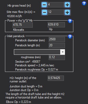
- Enter the gross head Hb and the site max flow (+ and − buttons to adjust).
- Enter H2, the runner outlet height above the tailwater level.
- Read the junction duct and elbow lines: they appear when the draft tube cannot be vertical.
- Hb, gross head (m): difference in altitude between the surface of the upstream reservoir and that of the downstream reservoir. It is an available pressure, not a velocity: the whole method of the window follows from this.
- Site max flow (m³/s): maximum flow that can be turbined. The software also shows it in m³/h. The + and − buttons adjust it by steps.
- H2, runner outlet height (m): height between the tailwater surface and the runner outlet, or its axis if the shaft is horizontal. It sets the pressure under the runner, hence the cavitation risk: the larger H2, the lower the pressure at the runner outlet.
- Junction duct and elbow: if the draft tube length and H2 do not allow a vertical draft tube, Heliciel says so and adds a horizontal junction duct and an elbow, showing their length and head losses.
Example
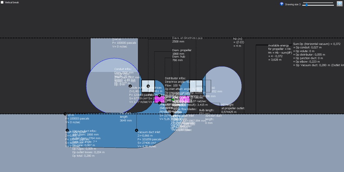
The vertical view shows the headwater and tailwater levels, the height H2 and the draft tube with its elbow.
Inlet penstock: velocity and head loss
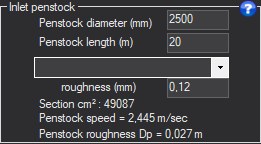
- Enter the penstock length and diameter.
- Choose the material in the list, or enter the roughness.
- Read the velocity and head loss: if the loss is high, increase the diameter.
Inputs: length (m), diameter (mm), roughness (mm), typed directly or set by choosing a material in the list.
Results: section (cm²), velocity in the penstock (m/s), friction loss (m), computed with the Colebrook formula.
Every metre lost in the penstock is taken from the head the runner receives (Hn = Hb − path losses). A penstock that is too small accelerates the water, and the loss grows roughly as the square of the velocity.
Example
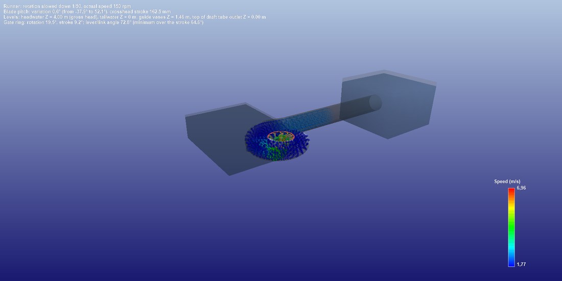
The whole installation in 3D: the penstock connects the headwater reservoir to the spiral casing.
Site power: ρ·g·Q·Hb

- Enter the gross head and the flow: the site power updates.
- Compare with the shaft power in the Results tab.
This block shows the gross site power, P = ρ·g·Q·Hb, in kilowatts and in horsepower, from the maximum flow and the gross head of the tab. It is the physical ceiling: path losses reduce it to ρ·g·Q·Hn, the power available at the runner, and the runner converts part of it into shaft power. These three levels are plotted in the Results tab.
Example
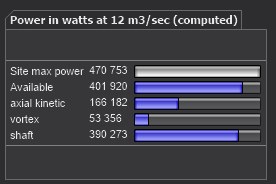
The power chart: maximum site power, available power, axial kinetic power and shaft power.
Going further
The Hydro Turbine design reference page presents the complete method and a worked case. The other help pages of the window:
 Global site map
 Mecaflux
 Tutorials Mecaflux Pro3D
 Tutorials Heliciel
 Tutorials Heliciel PRO CFD
 Mecaflux Store
 Compare software functions
 Quotes, Orders, Payment Methods
 project technical studies