
Blade root radius of a propeller or wind turbine: sizing the hub
The blade root radius of a propeller or wind turbine is the distance between the axis of rotation and the base profile of the blade's first element: it is where the blade begins. This radius sets the size of the hub and decides how much of the rotor disc the blade actually works. We look at it here on a wind turbine, but the approach is the same for propulsive propellers and for power-extracting rotors.
In this page:
- The blade root radius, where the blade begins
- Why lift is low near the hub
- Bending at the blade root
- Choosing the blade root radius of a wind turbine or propeller
- Leakage at the blade root and ventilation fans
1: The blade root radius, where the blade begins
Heliciel cuts the blade into elements, from the root to the tip. The blade root radius is therefore the radial position of the first of these elements. Between the axis and this radius there is only the hub, which produces no useful thrust.
You enter the blade root radius in millimetres in the "Radius mm" group, or adjust it with the Blade base radius (% of blade tip radius) slider. Heliciel then distributes the elements between this radius and the blade tip radius.
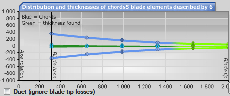
Distribution of chords (blue) and thicknesses (green) of the blade elements, as you enter them in Heliciel. The vertical line marks the blade root: the hub lies to its left, the blade to its right.
2: Why lift is low near the hub
The drag and lift forces accumulated along the blade concentrate at the blade root. Yet this is also where each element works the least. Because of the small radius, the apparent speed there is lower than at the blade tip. Lift varies with the square of that speed: for the same area, an element close to the hub lifts much less than an element at mid-blade.
To keep some lift near the blade root, we can widen the elements as they approach the axis. This extra width also increases the relative thickness of the profiles near the root and, with it, the mechanical strength of the blade of a propulsive propeller or a wind turbine.
The screenshot below, taken from Heliciel, shows the blade of a small wind turbine. The chords of the elements near the blade root are larger than those at mid-blade. Yet in the lift distribution graph, these elements lift less. The cause is the lower apparent speed at the blade root, and lift grows with the square of the apparent speed.
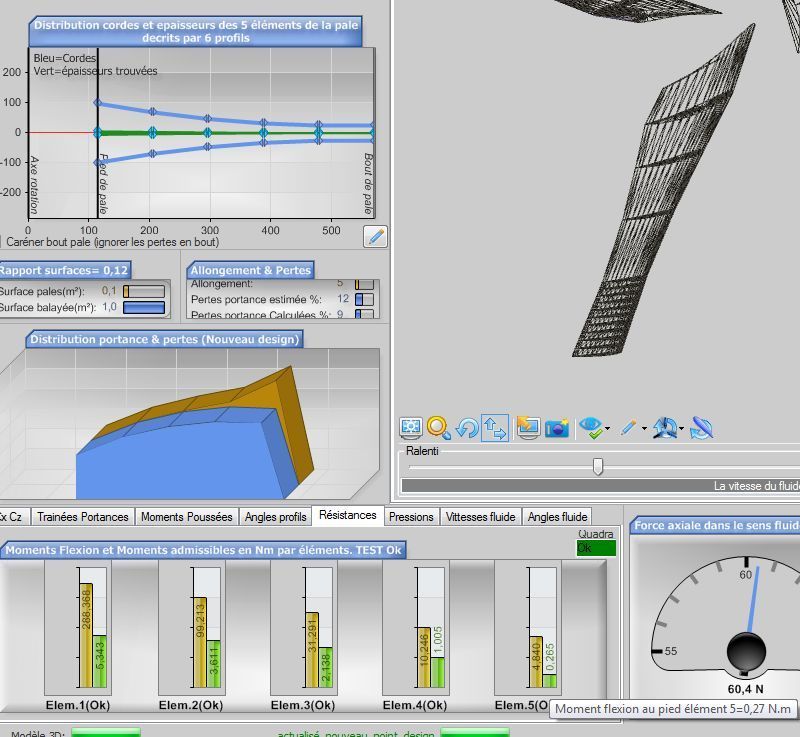
Bottom left, the lift distribution: lift falls towards the blade root despite wider chords, and the gold graph, which ignores losses, rises above the blue one at the blade tip. Below, the strength check, element by element.
Note also the lift losses caused by leakage at the blade tip: the gold graph shows the lift without these losses, the blue one what remains.
3: Bending at the blade root
The strength check graph shows that the allowable bending at the blade root (in yellow) is greater, thanks to the wide chords in that zone. Heliciel shows the calculated bending in green. Each element accumulates the bending of the elements further out: the bending at the blade root is therefore the sum of the bending moments of all the other elements. Even if the root itself generates little bending, it is the one that carries the highest bending moment. We detail this check in the page on the mechanical strength of a propeller or wing blade.
If we wanted the elements close to the blade root to produce effective lift, the blade would have to be considerably wide. The cost of material, compared with the return, leads us to concentrate on strength, and therefore on thickness.
4: Choosing the blade root radius of a wind turbine or propeller
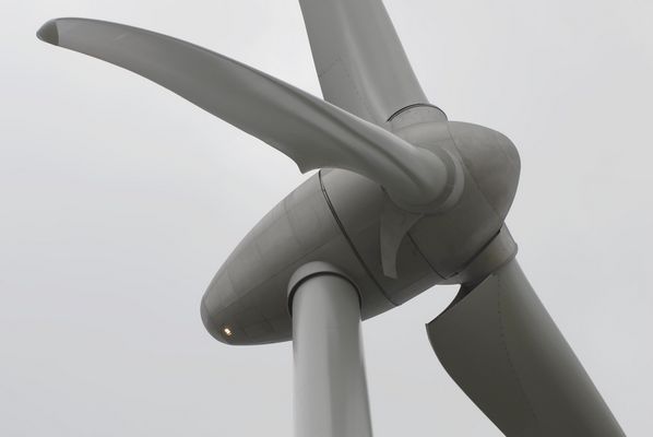
This reasoning leads manufacturers to draw blade roots that are generally close to round, without trying to bring the blade as close as possible to the axis.

A round wind turbine blade root attached to the hub: the blade makes no attempt to get closer to the axis.
Other manufacturers refuse to waste a single scrap of surface and extend the profile all the way to the hub.
A blade whose chord stays wide down to the hub.
It is very pretty. The extra manufacturing cost must nevertheless be justified by the efficiency gain over the years of operation: if it is purely aesthetic, it is true that it looks impressive.
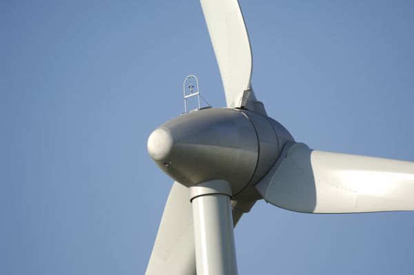
Another example of a blade widened near the hub.
At the other extreme are the propellers of the Wright brothers. Their engine was weak and every gram of thrust counted: the blade root radius is 0 mm.
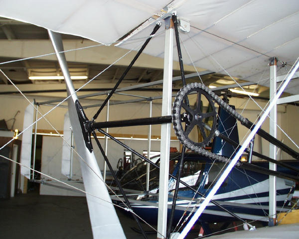
A Wright-type propeller driven by a chain: the blades start at the axis.
Let us keep the rule of choice in mind: a small blade root radius gains area, but that area lifts little and carries the maximum bending; a large radius loses area, but concentrates the blade where lift is greatest. For a propulsive propeller or a wind turbine, we therefore compare the two designs in Heliciel and keep the one that gives the best efficiency for sufficient strength.
5: Leakage at the blade root and ventilation fans
Like the blade tip, the blade root can become a leakage path for the fluid, because of the overpressure on the pressure side and the suction on the suction side. Besides the efficiency losses they cause, these leaks at the root and the tip can defeat the purpose of the propeller when its goal is to pressurise a fluid. This is the case for ventilation and fan propellers, and for axial pumps and jet ski turbines.
In these cases, we increase the blade root radius considerably. The pressure rise generated by the propeller is then concentrated in the zone where lift is greatest, at about 0.75 times the blade radius, and we avoid the zone of low pressure variation near the axis. Leakage decreases. As for tip losses, since the propeller is ducted, they become minimal.
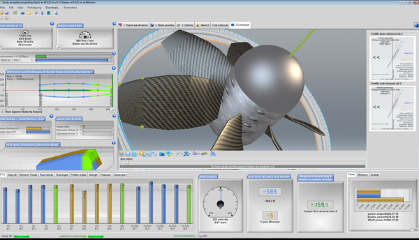
Diagram of a ducted propeller: the hub is wide and the blades work in the zone of maximum lift.
To go further, we can look at how the propeller, the blade and the profile are cut into elements in Heliciel, or how to size a wind turbine or wind motor with its hub in mind.
 Global site map
 Mecaflux
 Tutorials Mecaflux Pro3D
 Tutorials Heliciel
 Tutorials Heliciel PRO CFD
 Mecaflux Store
 Compare software functions
 Quotes, Orders, Payment Methods
 project technical studies