
see also: evolution propeller design methods
Blade elements applied: a first propeller One optimal point: pressure and boundary layer BEM vs CFD on an aircraft propellerThe propeller as a rotating wing: how propeller calculation works
Propeller calculation rests on a simple idea: the propeller is a rotating wing, whose blades use lift to create thrust. This idea lets us predict the performance of a propeller from the airfoils of its blades. We only have to account for the fact that the speed of the air or water changes with the distance from the axis.
Whether it is meant to capture energy or to propel a fluid (or a vehicle), building a propeller requires two things together: the prediction of its performance and the geometric definition of the blade, which lets us produce the drawings or the 3D model.
In this page:
- Propeller calculation: the Wright brothers' idea
- Blade element calculation: cutting the blade into slices
- Induced velocities and propeller performance
1: Propeller calculation: the Wright brothers' rotating wing idea
The history of propeller calculation methods shows a wide variety of approaches. The one that let people take off predicted performance from the geometry of an airfoil.
The Wright brothers had tested miniature airfoils in a wind tunnel. These tests let them calculate, then extrapolate, the performance of their wings. They therefore knew the thrust needed to balance the drag of those wings, thrust supplied by two propellers.
Propeller efficiency mattered all the more because they did not have the power of today's engines. Powered flight stayed out of reach as long as no engine of reasonable weight could deliver the required thrust. Finding the best power-to-weight ratio was essential, but wasting that power with a poor propeller efficiency was out of the question.
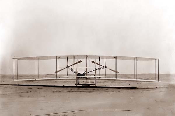
An engine, wings, two propellers: the Wright brothers also had a method.
The Wrights decided to treat the propeller as a rotating wing, to transfer their wing prediction method to it, and they took off. Natural idea or stroke of genius? We leave you to judge. Modern propeller calculation methods were born.
2: Blade element calculation: cutting the blade into slices
To apply wing airfoil data to a blade, one difference must be taken into account. The apparent speed seen by the airfoil depends on its distance from the axis: it is low near the hub and high at the tip. We therefore have to calculate performance while accounting for these speed variations.
To do so, we cut the blade into slices, from root to tip. Each slice is a blade element, studied at the relative speed it meets at its position along the radius. The author's experience is that beyond about ten elements, accuracy improves little while computing time grows a lot.
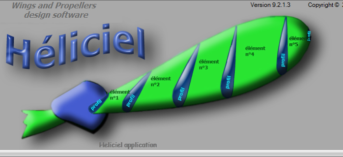
A blade cut into elements numbered from root to tip: each element carries its airfoil and sees its own relative speed.
Heliciel calculates the lift and drag of each element from its relative speed. It then projects these forces into thrust and torque, and sums them to obtain the overall performance of the propeller.
3: Induced velocities and propeller performance
The blade element method alone is not enough, because the blade itself modifies the flow it passes through. We therefore couple it with other methods that account for induced velocities. The blade element method combined with vortex theory relies on airfoil performance databases to solve the system of equations that gives the propeller's performance.
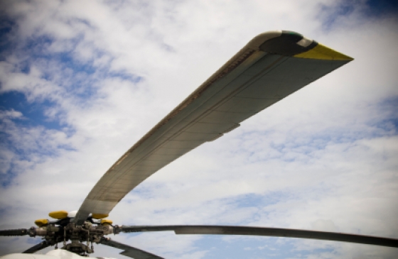
A helicopter rotor blade: a long, narrow wing turning around an axis.
To go further, we can read the blade element theory, follow the evolution of calculation methods or study the efficiency of a propulsive propeller.
 Global site map
 Mecaflux
 Tutorials Mecaflux Pro3D
 Tutorials Heliciel
 Tutorials Heliciel PRO CFD
 Mecaflux Store
 Compare software functions
 Quotes, Orders, Payment Methods
 project technical studies