
Propeller shroud and ducted propeller: tip losses, gain and limits
A propeller shroud is a ring or nozzle around the blades that stops the fluid from flowing around the blade tips. It removes the tip vortex, a source of loss for short or heavily loaded propellers. A ducted propeller therefore gains efficiency, but it pays for that gain with the drag of the duct and a tip clearance to keep tight. Heliciel lets you estimate the benefit by ticking the ducted propeller option.
In this page:
- Why a propeller loses energy at the blade tip
- Reducing blade tip losses without a shroud: elliptical blades and winglets
- Simulating a ducted propeller in Heliciel: the option and its limits
- Wind turbine shroud and the Betz limit
- Ducted propulsion propellers: boats and tugs
- Shrouded fans and axial pumps
1 : Why a propeller loses energy at the blade tip
We saw it with the wing: the pressure is higher under the blade (the pressure side) than on top (the suction side). At the blade tip nothing holds the fluid back, so it flows around the end from the high-pressure side to the low-pressure side. This creates a tip vortex, and lift collapses over the part of the blade near it.
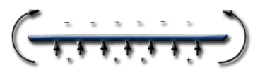
View of a blade tip: the arrows under the blade show the pressure-side overpressure, those above it the suction-side depression, and the curved arrows on each side the fluid flowing around the tip.
The shorter the blade, the more this disturbed zone weighs in the total area: the efficiency loss of a propeller or wing grows as the blade gets shorter. We detail the mechanism on the page about wing and blade tip losses, and the link with aspect ratio on the aspect ratio page.
2 : Reducing blade tip losses without a shroud: elliptical blades and winglets
A first remedy is to give the blade or wing an elliptical shape and a length that concentrate lift as far as possible from the tip. The fluid then finds less pressure difference to equalise at the end.
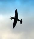
The Spitfire and its elliptical wings, which concentrate lift as far as possible from the wing tip to limit leakage.
A second remedy, which can be combined with the first, places a barrier that blocks the fluid at the blade tip: these are the winglets of wings.
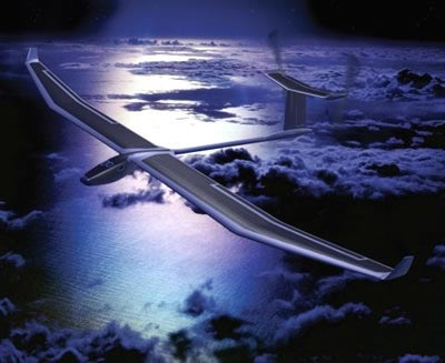
The upturned wing tips of this solar aircraft act as a barrier against the flow around the tip.
A propeller can also be fitted with winglets, which is done on some helicopters. Heliciel can study this case: the page on the winglet at the tip of a blade or wing describes the settings and their assumptions. A winglet never removes the flow around the tip completely, whereas a shroud blocks it all the way round.
3 : Simulating a ducted propeller in Heliciel: the option and its limits
Another way to cut blade tip losses is to duct the propeller. Heliciel can simulate a shroud: if you tick the ducted propeller option, blade tip losses are taken as zero in the calculation. The option sits in the shroud and duct block of the data banner, which the page on choosing between free flow, ducted propeller and forced duct describes in detail.

Chart of the chord and thickness distribution of the blade elements, with the box « Duct (ignore blade tip losses) » ticked: the elements are then calculated without tip loss.
This setting is not completely realistic, and we would rather say so. The blade tip rubs against the fluid that stagnates in the boundary layer of the duct, which adds a resisting torque and lowers efficiency. In practice we keep a clearance larger than the thickness of that boundary layer, so leaks can remain. Heliciel therefore gives slightly overestimated efficiencies.
The option remains useful for assessing the benefit of a shroud around the propeller: we compare the calculation with and without the duct, then weigh that gain against the cost and the drag of the shroud itself, which the calculation of the propeller alone does not see. Once the shape is settled, the shroud can be exported with the propeller as STL, IGS or OBJ: see the 3D propeller exports.
4 : Wind turbine shroud and the Betz limit
Some wind turbine designers use a shroud to increase efficiency, and some even claim to exceed the Betz limit with this system. One point is beyond dispute: the shroud minimises tip losses by creating a barrier against the flow around the tip, as winglets do.


Three shrouded wind turbines: the nozzle surrounds the propeller and sets the passage section of the wind.
The Betz limit, however, is hard to discuss when the propeller diameter is the only reference. The power coefficient of the propeller (Cp) is:
Cp = Pshaft / (0.5 × ρ × V³ × Adisc)
where Pshaft is the shaft power of the propeller (W), ρ the fluid density (kg/m³), V the undisturbed fluid speed (m/s) and Adisc the area actually captured (m²). The Betz limit, 16/27 or about 0.593, refers to that captured area. If you take the area swept by the propeller, located at the bottom of the inlet cone formed by the shroud, you divide by an area smaller than the one that captures the wind, and the result is distorted.
If someone announces a wind turbine efficiency above 0.59, check that the disc area used corresponds to the area actually captured. Another trick is to draw off the plug of fluid that forms behind the propeller, using profiled rings that draw on energy from outside the stream to create a depression at the rear. The area actually captured changes there too.
The best energy-capture propellers reach something like 70 to 80% of the Betz limit. Shrouded systems have their advantage, since they reduce tip losses and raise the efficiency of the propeller, but never above the Betz limit. The gain has to be weighed against the extra manufacturing cost: with the added material, one could often increase the propeller diameter, and therefore the power of the whole system. The Froude theory and the Betz limit give the demonstration.
5 : Ducted propulsion propellers: boats and tugs
When the site limits the propeller diameter, and the medium does not allow longer blades to reduce tip losses, some boat builders duct their propellers. When a propeller must deliver a strong thrust with a small diameter, tip losses become very large. This is the case for tugs.

Ducted propellers of tugs, seen from the stern of the hulls.
In this case the shroud can bring a significant efficiency gain. The figure « up to 50% » is quoted, but we have not verified it here: the gain depends on the propeller loading, and the calculation with and without the duct option gives it for your propeller. Since tip losses are no longer a concern, the chord at the blade tip can be large, because the blade stays effective all the way to the end.
The shroud has a price: it creates a drag proportional to the square of the ship's speed. Above a certain speed, this drag destroys the gain made on tip losses. A ducted propeller therefore suits slow vehicles. To size such a propeller, we start from the page on propulsion propellers, then follow the propulsive efficiency during construction.
6 : Shrouded fans and axial pumps
This solution is applied as a matter of course to fan propellers, since the propeller is already built into a duct. As tip losses are no longer a concern, the chord at the blade tip can be large. We see it for instance on this industrial ventilation unit, which has to deliver a high flow rate:
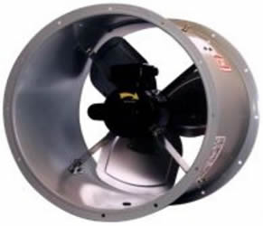
High-capacity industrial fan: the propeller turns inside a cylindrical casing.
For propellers that must create a pressure difference, such as fans, axial pumps or jet-ski propellers, tip losses are no longer only an efficiency problem. Leakage around the tip can prevent pressure from building up and defeat the purpose of the fan or pump. The shroud must therefore pass very close to the blades.
The radius at the blade root must also be set with care to avoid leaks. At low speed, near the centre, the pressure difference created by the elements close to the hub lets leaks through. To prevent this, the blade root radius will, as a rule of thumb, be more than 50% of the blade tip radius:

Ducted ventilation fan: the hub takes up a large share of the radius.
The blade root radius is set in the 2.1: Blade dimensions tab: see sizing the blade root radius. For an axial pump or a ducted fan, forced duct mode replaces the free-flow assumption: see modelling a propeller pump or a fan.
To go further, we can compare the ducted propeller calculated by blade element momentum (BEM) with a full simulation of the flow in the duct: see the ducted fan calculated by CFD with the PRO extension. We can also return to the choice of diameter and blade length, the first lever against tip losses.
 Global site map
 Mecaflux
 Tutorials Mecaflux Pro3D
 Tutorials Heliciel
 Tutorials Heliciel PRO CFD
 Mecaflux Store
 Compare software functions
 Quotes, Orders, Payment Methods
 project technical studies