
Wind turbine and propeller blade: shape, profiles, twist and manufacturing
A propeller or wind turbine blade is a rotating wing: an aerodynamic or hydrodynamic profile, repeated along its length, whose chord and pitch angle change with the radius. A propeller or a wind turbine essentially consists of a hub and blades. The shape of the blade (profiles, chord, twist) results from a compromise between the lift it produces, the mechanical strength it needs and the material we accept to put into it. This page explains that compromise, then reviews the materials and manufacturing techniques for aircraft propellers, boat propellers and wind turbines.
Contents:
- Wind turbine blade and propeller blade: a rotating wing
- Blade twist and profile pitch angle
- Variable pitch and number of blades
- Blade shape: chord distribution and aspect ratio
- Making an aircraft propeller blade: wood, duralumin, steel, carbon
- Making a boat propeller blade: moulding
- Making a wind turbine blade: glass fibre, pultrusion, filament winding
1: Wind turbine blade and propeller blade: a rotating wing
The propeller blade, or the wind turbine blade, can be considered as a rotating wing. Its shape is defined by profiles chosen for their aerodynamic performance. These profiles are distributed along the blade to achieve the best compromise between blade strength and lift production.
The profile of a section is characterised by its chord (the line joining its leading edge to its trailing edge) and by its thickness. Profiles near the blade root are thicker, because they carry more load. Those at the tip are thinner and work at higher speed.
2: Blade twist and profile pitch angle
The rotation of the propeller creates an apparent speed and angle that vary with the position of the point observed along the blade radius. The pitch angle is the angle between the profile chord and the plane of rotation; it equals the sum of the apparent angle and the angle of attack. To keep an optimum angle of attack, the pitch angle of the profiles must therefore be adjusted to the apparent speeds along the blade.
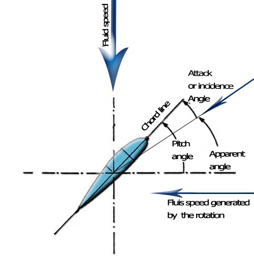
On a blade profile: the fluid velocity and the velocity created by the rotation give the apparent velocity. The apparent angle is its angle with the plane of rotation, the pitch angle is that of the chord, and the angle of attack is the difference between the two.
The pitch angle of the profiles therefore varies along the blade and causes its twist. The twist of a propeller or wind turbine blade is the angle measured between the profile chord at the blade root and the profile chord at the blade tip. It is tied to the operating point: if the operating point changes, the twist should be changed. But propeller and wind turbine blades are generally rigid, so their twist is fixed.
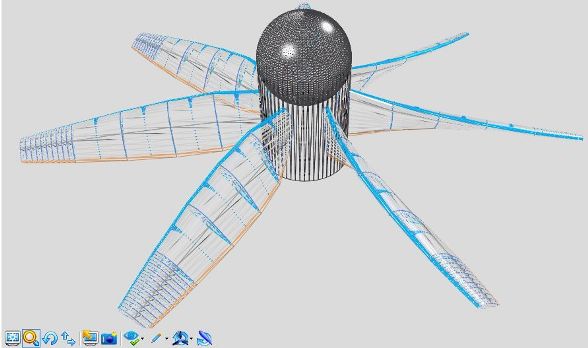
A six-blade propeller modelled in Heliciel: following one blade from the hub to the tip, you can see the profiles turn gradually about their axis. That is the twist.
A change in rotation speed or fluid speed from the design operating point degrades the performance of the propeller or wind turbine.
3: Variable pitch and number of blades
Pitch variation means rotating the blade about its axis, so as to correct this loss of performance. On wind turbines, it also serves to regulate the rotation speed.
The number of blades of the turbine or propeller varies with the torque and speed at the operating point. Thus a water-pumping wind turbine does not have the same number of blades as an electricity-generating wind turbine. A sailboat propeller has a very different blade shape from an outboard propeller.
4: Blade shape: chord distribution and aspect ratio
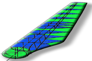
A wind turbine blade modelled in 3D and split into elements, each carrying its profile: this is the split used by the blade element method.
We saw in the article on profile chord distribution that the lift of wind turbine and propeller blades must be spread as far as possible from the tip leakage. This leads to an elliptical distribution of lift, but not of chords. The blade elements move more slowly near the root; the area must therefore be increased there, to respect the elliptical lift distribution, whether for a wind turbine, a propeller or a tidal turbine.
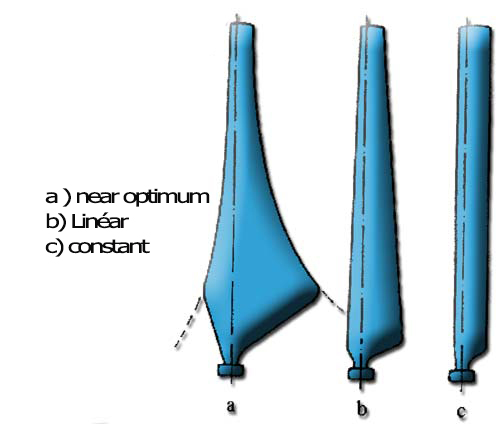
Three chord distributions for the same blade: (a) close to the optimum, wide at the root and narrow at the tip; (b) linear; (c) constant, the simplest to manufacture.
A compromise between the extra material cost and the efficiency gained must be assessed, because the material used at the blade root becomes very large. A high aspect ratio generally gives better efficiency. But for boat propellers, the blade length is limited by the maximum depth of the propeller shaft, by the tip speed (which quickly causes cavitation when the blade nears the surface) and by the limited draft. These constraints impose blade shapes very different from those of aircraft or wind turbine blades.
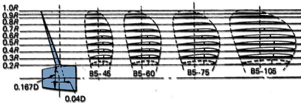
Developed outlines of five-blade boat propeller blades (B5 series, from B5-45 to B5-105): the larger the area ratio, the wider the blade. These short, wide shapes have nothing in common with an aircraft blade.
5: Making an aircraft propeller blade: wood, duralumin, steel, carbon
The material and structure of the blade are taken into account in the strength calculation of the propeller or wing in Heliciel. A quick tour of blade construction techniques and materials will help us.
Heliciel takes the material and structure of the blade into account in its strength calculation: propeller or wing strength calculation.
Wood. For wooden propellers, those of early aviation and those still fitted to light aircraft, the best material is walnut. Mahogany, rosewood, ebony, beech, elm, ash, boxwood or maple can also be used.
Duralumin. When metal replaced wood, duralumin was chosen in the great majority of cases. It could only be chosen after years of work by metallurgists to perfect its forging. Around 1920, duralumin could be drawn and rolled well, but not forged in volumes large enough to make a propeller blade. Under the hammer, it behaved somewhat like a block of rubber: it relaxed, instead of gradually taking shape as a block of steel does. Today, duralumin blades are made by forging and stamping, with well-mastered techniques.
Magnesium. Naturally, people looked to replace duralumin with an even lighter metal: magnesium alloy. Blade lightness is an asset, because the centrifugal forces, which reach several tens of tonnes on large propellers, are proportional to the density of the material. Lightening the blade therefore reduces the sections, the weight and the bulk of the hub parts. On the other hand, forging magnesium blades takes more powerful tooling than duralumin, and die-forging brought a solution for making the blades.
Steel. It is used for large propellers. The blade is then hollow, made of two pressed half-shells welded around their edge and fitted with internal stiffeners. The strength of the welds took a long time to perfect, because the sheets "slipped" against each other in the first versions.
Carbon. It is used more and more and seems to be taking over, thanks to its lightness and strength. It demands perfect command of moulding to obtain good balance and no defects.
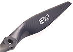
A carbon aircraft propeller (model size): the blade is moulded in one piece.
6: Making a boat propeller blade: moulding
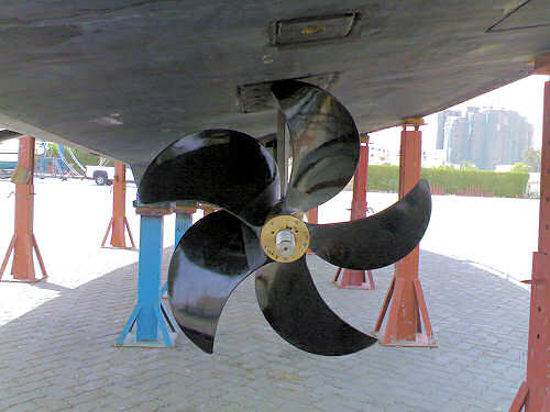
Boat propeller blades are generally moulded. A mould bed is built first, and surfaced to the pitch of the propeller with a board that turns and slides around an axis, guided by a rail that gives the pitch.
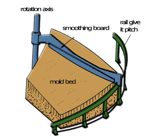
The smoothing board turns about the rotation axis and slides along the rail: the rail gives the pitch, and the board surfaces the mould bed to that pitch.
The mould bed is hollowed out and shaped using boards cut to the shapes of the blade profiles.
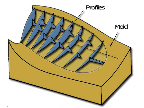
Boards cut to the profile shapes, set along the blade, give the hollow of the mould its shape.
The top of the mould is made the same way, and the blade is then cast.
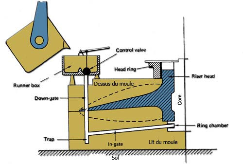
Section of a casting mould: the metal runs down the down-gate, fills the cavity between the mould bed and the top of the mould, and the riser head at the top makes up for shrinkage as it cools.
A new generation of propellers is appearing with carbon, which is entering and taking hold in the boat propeller market.
7: Making a wind turbine blade: glass fibre, pultrusion, filament winding
The materials used today are mainly glass or carbon fibre impregnated with polyester or epoxy resin. Wood is still used mostly for small two-blade wind turbines, whose two blades are cut from the same piece of wood. Connecting wooden blades to a hub can prove delicate, because of fatigue and centrifugal force.
For small wind turbines, glass fibre pultrusion is sometimes used. Pultruded blades pass through a die that gives them their profile, but the chord distribution is necessarily constant. Moulded blades therefore allow more efficient aerodynamic shapes than pultruded blades.
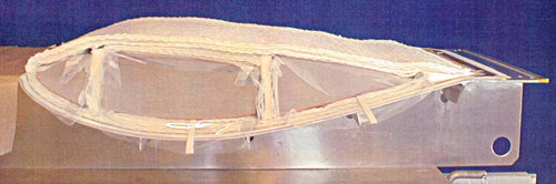
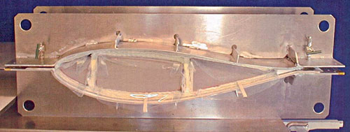
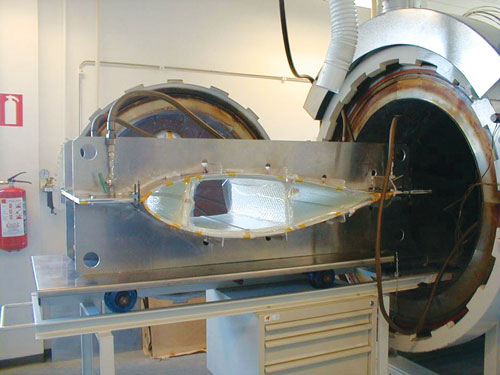
Three stages in building a moulded blade: the shell and its internal stiffeners, the section in place in its mould, then the mould in front of the chamber where the resin cures.
Another fibre and resin method, filament winding, consists of winding a resin-coated thread around a core that is rotated on a lathe.
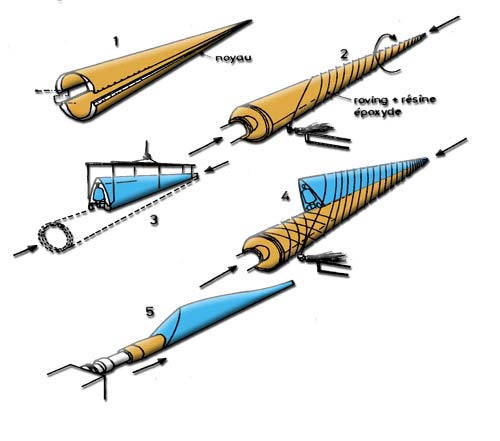
The five stages of filament winding: the core (1), winding the thread and epoxy resin (2), shaping (3 and 4), then the finished blade (5).
Here too, carbon is appearing, but it is mostly kept for small wind turbines, because of the price of the raw material.
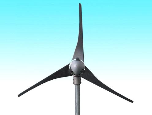
To go further, we can see how blade twist and profile pitch angle are calculated, how to choose the blade root radius, or come back to Heliciel's "rebuild" function, which recalculates the twist for a given operating point.
 Global site map
 Mecaflux
 Tutorials Mecaflux Pro3D
 Tutorials Heliciel
 Tutorials Heliciel PRO CFD
 Mecaflux Store
 Compare software functions
 Quotes, Orders, Payment Methods
 project technical studies