
3D Models of Propeller Blades and Wings: 3D View and IGES, STL, STEP Export
Heliciel builds propeller blades (airplane, boat, wind turbine, fan) and wings in 3D, shows them in its animated 3D engine, then exports them as IGES, STL or STEP for CNC machining, rapid prototyping and CAD. Surface-smoothing functions improve the surface finish and make it possible to build high-quality blade prototypes. A DirectX .X export and other formats serve games, simulators and animated films.
On this page:
- Heliciel's 3D engine: viewing the blade and its forces
- Exporting a propeller blade as IGES, STL or STEP
- Importing the blade into SolidWorks or Fusion 360
- A prototype with adjustable blades
- Exporting a blade as a DirectX .X file
 1: Heliciel's 3D engine: viewing the blade and its forces
Heliciel has its own animated 3D engine: it lets you view your project in three dimensions and in motion. Beyond looks, the ergonomic benefit is real. The notion of blade (or wing) elements and of profiles is made visible. By selecting an element on the 3D model, you display the parameters that concern it: the plane of the base profile and that of the tip profile of the element appear at the edge of the window, with their pitch angle and fluid angle information.
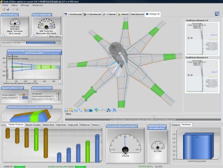
A multi-blade wind turbine in the Prototype 3D tab. The two profile planes on the right belong to the selected element.
The force, torque, drag, lift and resistance vectors are visible for each element. Analyzing the quality of the blade and the forces acting on it then becomes straightforward.
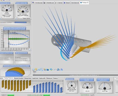
The lift (blue) and drag (gold) vectors of each blade element.
Three display modes (points, wireframe or solid) give a precise view of the profile shapes and their pitch angle.
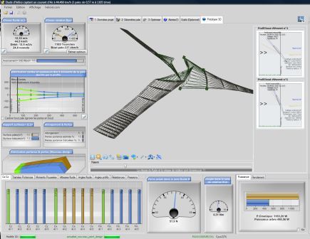
A blade in wireframe display: each profile and its pitch angle can be told apart.
An animation of particles flows through the blade. Their trajectories are programmed from the induced velocities: they combine the tangential and axial induced velocities, and give a picture of the phenomenon. The axial induced velocity is shown as a spin motion proportional to the calculated intensity.
Moving particles around the propeller:
A steerable-blade simulation is available directly from the 3D model interface. It corresponds to the pitch variator, described on the page about pitch angle and blade pitch:
You can also choose the blade texture that best represents your project.
2: Exporting a propeller blade as IGES, STL or STEP
The IGES or IGS format (Initial Graphics Exchange Specification 5.3) is the most common 3D format. Almost every computer-aided design and drafting (CAD) system recognizes it, as do stereolithography machines and other prototyping machines. Heliciel exports your blade geometry as IGES: the entities produced are entities 126 and 128, that is, spline surfaces and spline curves, which describe the twisted surfaces of a blade well.
The exports are in the File menu. Heliciel exports the 3D shape of the blade in a frame where the x axis is the rotation axis, the y axis is the blade axis, and the origin is the intersection of the two. For IGES, two output scales are offered: scale = 1, and scale = 10, which avoids rounding errors for small-diameter propellers, under 100 mm. The menu also offers a fairing export in IGS.
- IGES: the blade as spline surfaces, for CAD and machining;
- STEP: the complete propeller or the propeller without hub;
- STL: the complete propeller, the propeller without hub, the blade alone, the cyclic part or the fairing, as a triangle mesh for 3D printing and prototyping;
- OBJ (complete propeller and fairing) and GLB (propeller for the 3D web): mesh formats readable by most 3D software.
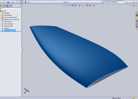
The blade exported as IGES (spline surfaces), opened in a CAD system that reads these entities.
3: Importing the blade into SolidWorks or Fusion 360
For users of the SolidWorks or Fusion 360 CAD software, here is an example of creating a propeller blade with SolidWorks. Fusion 360 follows the same steps. Use the File menu to export your blade as IGES, then open the IGES file with SolidWorks.
Note: since version 2018, SolidWorks has changed the default import options for curved-surface IGES files. A setting may be needed: in the system options, under Import, untick "3D Interconnect" and tick "Import multiple bodies as parts".
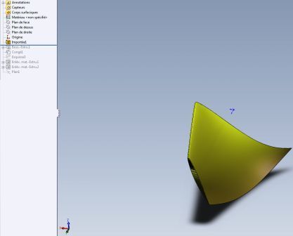
The IGES blade imported into SolidWorks.
The smoothed shape of your blade appears in a part whose x axis matches the propeller's rotation axis and whose y axis matches the blade axis. To make handling and assembly easier, display the origins in SolidWorks' display settings.
To connect the blade to a "Heliciel" type hub in an assembly, we create a cylindrical part: we extrude a circle from the top plane up to the imported blade shape. This part acts as the connecting interface between the blade and the hub.
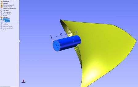
The cylinder extruded at the base of the blade serves as the interface with the hub.
To make future blade assembly easier, we create a sketch containing only one construction line, coincident with the x axis.
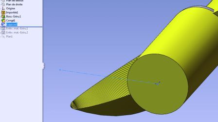
The sketch reduced to a construction line on the x axis.
When Heliciel builds your propeller, we place a notch coincident with the plane of rotation, to allow the pitch angle to be adjusted. The plane of rotation of the propeller is bounded by the y and z axes.
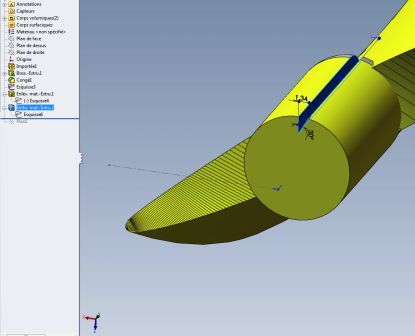
The notch that marks the plane of rotation.
A two-part hub then sandwiches the cylindrical part of the blade, thanks to two housings provided for that purpose.
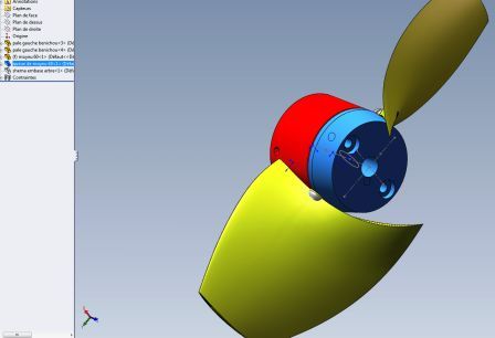
Two blades assembled in a two-part hub.
4: A prototype with adjustable blades
The Heliciel team produces and builds blade prototypes for some customers. It uses an adjustable hub type (registered design), the one we took for the assembly above. Here is an example of a prototype built by Heliciel:
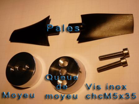
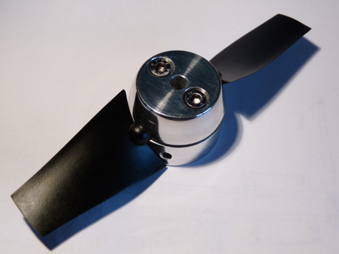
On the left the parts (blades, hub, hub tail, stainless screws), on the right the assembled propeller.
For more details on assembling "Heliciel" type adjustable hubs (registered design): assembly of the adjustable-blade prototype propeller.
5: Exporting a blade as a DirectX .X file
The .X format is the standard 3D format of DirectX. Some numerically controlled machines can read it directly, so a blade exported this way can be machined. It also lets you quickly integrate realistic, functional 3D propellers into games, simulators or animated films. The .X file reader built into Heliciel lets you check the result of exporting a propeller blade or a wing; it shows the file as points, triangles or solid.
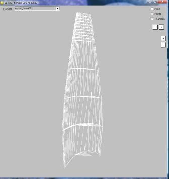
The .X file reader, here on a blade shown as a triangle mesh.
To go further, we can look at how the blade is built before export with blade twist and pitch angle, how to set the shape of the blade generatrix to get curved blades, or how to force the angle of attack of the profiles before freezing the geometry.
 Global site map
 Mecaflux
 Tutorials Mecaflux Pro3D
 Tutorials Heliciel
 Tutorials Heliciel PRO CFD
 Mecaflux Store
 Compare software functions
 Quotes, Orders, Payment Methods
 project technical studies