
The measured geometry of the NR640 propeller, a replica of the Clark Y propeller of NACA Report 640, imposed on Heliciel in reverse engineering, and its C_T, C_P and efficiency compared with the University of Illinois measurements over the whole J sweep.
Validation: Wageningen B-series
Reverse engineering
Reading Kt, Kq and J
Heliciel MCP connector
Validating Heliciel against wind tunnel measurements: the NR640 aircraft propeller
The Wageningen B-series lets Heliciel be compared with marine propellers tested in a towing tank. For aircraft propellers, no series is as standardized. There are, however, propellers whose geometry and measured performance are both known. One of them has a particular history: the Navy 5868-9 with Clark Y sections, a 10-foot propeller tested by NACA in 1938 (Report 640). Researchers at the University of Illinois reproduced it as 3D-printed models, under the name NR640, measured in a wind tunnel with their geometry surveyed. This page imposes on Heliciel the measured geometry of the 9-inch model, has it compute the performance over the whole advance ratio sweep, and lays the computed curves over the measured points.
| Speed | Element Reynolds numbers | J range | C_T: mean deviation [extremes] | C_P: mean deviation [extremes] | Efficiency: mean deviation |
|---|---|---|---|---|---|
| 6,000 rpm | 12,000 to 46,000 | 0.10 to 0.37 | −1.4 % [−4.6; +2.1] | −2.4 % [−4.3; +0.6] | +0.005 |
| 0.37 to 0.53 | +14.6 % [+6.4; +25.0] | +9.0 % [+3.7; +15.4] | +0.033 | ||
| 3,000 rpm | 6,000 to 23,000 | 0.21 to 0.32 | −1.8 % [−6.3; +3.0] | −2.0 % [−5.3; +1.4] | +0.001 |
| 0.32 to 0.53 | +39.4 % [+11.6; +65.5] | +24.8 % [+7.4; +39.0] | +0.059 |
1: The question, and what it does not cover
The question is the same as for the B-series: with an identical geometry, does Heliciel's BEM (Blade Element Momentum) model reproduce the measured coefficients? The comparison covers a sweep in J, not a single point.
What it does not cover:
- the measured model is a small, low Reynolds number propeller: 6,000 to 46,000 depending on the element and the speed (section 5). This is the domain of drones and scale models, not of an aircraft propeller. The comparison therefore tests the low Reynolds polars as much as the BEM itself;
- the model is 3D-printed, and its measured geometry departs from the design: 16.36° instead of 15° at 0.75 R, rounded blade tip. Heliciel was given the measured geometry;
- the full-scale propeller of Report 640 is not compared here. It ran in front of an engine nacelle, its published thrust is an effective thrust (thrust minus the change in nacelle drag) and its efficiency that of the propeller-engine unit: these are not the isolated propeller quantities that Heliciel computes;
- a single configuration is run: 2 blades, 15°, 9 inches, at two speeds. The database also holds 3- and 4-blade versions and a 5-inch model, not run so far.
2: The measured reference
The measurements come from the UIUC Propeller Data Site, volume 2, compiled by R. W. Deters (applied aerodynamics group of M. S. Selig, University of Illinois). For each propeller the database publishes the surveyed geometry (chord and pitch angle along the radius), the static coefficients and, in the wind tunnel, C_T, C_P and efficiency against J at several speeds. It states that its latest wind tunnel correction method is applied. The original propeller is described in NACA Report 640 (Hartman and Biermann, 1938). Linking the NR640 to that report rests on its name and on the agreement of its design geometry with figure 2 of the report: nearly constant pitch, P/D 0.63 between 0.6 and 0.75 R, maximum chord of 0.153 R near mid-radius.
Two speeds are selected for the 2-blade 9-inch model: 6,000 rpm (runs 6004 and 6068 of the database, 27 points from J 0.10 to 0.68), the highest Reynolds number available, and 3,000 rpm (run 3023, 9 points from J 0.21 to 0.64), for the Reynolds effect. On these same measurements, the maximum efficiency goes from 0.544 at 3,000 rpm to 0.641 at 6,000 rpm: the same propeller loses 10 points of efficiency when the Reynolds number is halved.
3: The geometry imposed on Heliciel
The model's surveyed geometry file has 18 stations, from 0.15 to 1.00 R. Heliciel receives them in reverse engineering mode: 228.6 mm diameter, 2 blades, 8 elements, a chord law tabulated on the 18 stations, and pitch angles read on the same table at each element root radius and at the tip. The interpolation is monotone (PCHIP): it passes through every station without oscillating between them. The table below reads back what Heliciel actually applied; chord and pitch angle match the table to the hundredth.
| Element | Station | Radius (mm) | r/R | Chord table / applied (mm) | Pitch angle table / applied (°) | Applied pitch ratio P/D |
|---|---|---|---|---|---|---|
| 1 | root | 17.7 | 0.155 | 13.50 / 13.50 | 41.53 / 41.53 | 0.431 |
| 2 | root | 29.8 | 0.261 | 12.02 / 12.02 | 37.30 / 37.30 | 0.624 |
| 3 | root | 41.9 | 0.366 | 14.99 / 14.99 | 30.85 / 30.85 | 0.687 |
| 4 | root | 53.9 | 0.472 | 17.38 / 17.38 | 24.15 / 24.15 | 0.665 |
| 5 | root | 66.0 | 0.577 | 17.26 / 17.26 | 20.10 / 20.10 | 0.664 |
| 6 | root | 78.1 | 0.683 | 15.59 / 15.59 | 17.50 / 17.50 | 0.676 |
| 7 | root | 90.2 | 0.789 | 13.21 / 13.21 | 15.90 / 15.90 | 0.706 |
| 8 | root | 102.2 | 0.894 | 10.28 / 10.28 | 14.70 / 14.70 | 0.737 |
| 8 | tip | 114.3 | 1.000 | 2.12 / 2.12 | 9.37 / 9.37 | 0.518 |
Three choices had to be made for lack of data, and they must be stated:
- section: the UIUC database only publishes chord and pitch angle. The section is the Clark Y of the original propeller, taken here as a single profile of Heliciel's database,
clarky_turbulent, over the whole blade. Yet the design thickness ratio goes from 37 % at 0.30 R to 8 % at 0.95 R: the blade root is represented by a much thinner section than the real one; - hub: no file gives its radius. The blade root is set at 0.155 R (17.7 mm), just above the first measured station;
- fluid: the air of Heliciel's aircraft propeller model, 1.012 kg/m³. The C_T and C_P coefficients do not depend on density; the Reynolds number does depend on the viscosity of the fluid used.
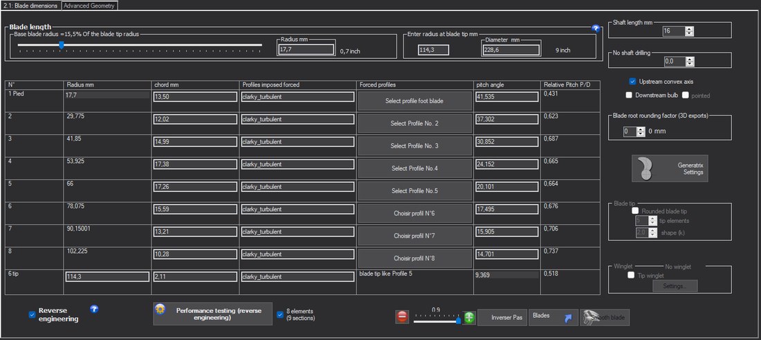 The reverse engineering grid after application: radii, chords, forced section, pitch angles and pitch ratios of the 8 elements, plus the tip
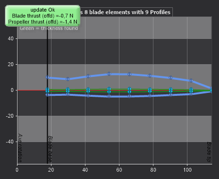 Blade outline and element stations, from the root (17.7 mm) to the tip (114.3 mm)
4: The 3D model, a visual check
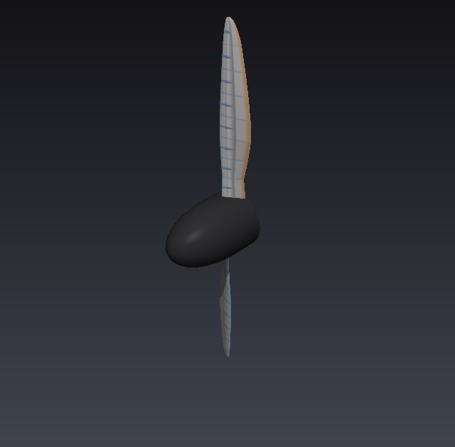
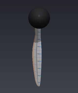
The 3D model is built by Heliciel from the imposed geometry. It serves as a visual check: narrow blade, maximum chord near mid-radius, strong twist from root (41.5°) to tip (9.4°), tip rounded by the surveyed chord.
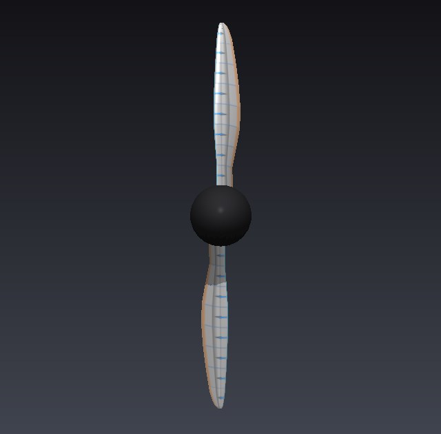 Front view |
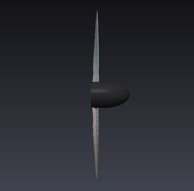 Side view: the twist |
 Three-quarter view |
 A single blade |
5: The J sweep at 6,000 rpm
Speed is held at 6,000 rpm and the advance speed swept from 2.29 to 16.0 m/s in 25 points, i.e. J from 0.10 to 0.70, in off-design mode: the imposed geometry is never recomputed. C_T and C_P are recomputed from the thrust, power, density, speed and diameter read in Heliciel's table, and agree with its own columns. Element Reynolds numbers, read at J = 0.437:
| Element | 1 | 2 | 3 | 4 | 5 | 6 | 7 | 8 |
|---|---|---|---|---|---|---|---|---|
| 6,000 rpm | 12,113 | 19,430 | 30,824 | 40,430 | 45,369 | 45,975 | 42,790 | 25,191 |
| 3,000 rpm | 6,057 | 9,715 | 15,412 | 20,215 | 22,684 | 22,987 | 21,395 | 12,596 |
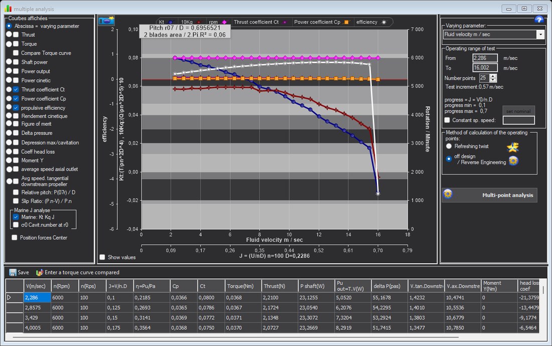 The sweep in Heliciel's multiple analysis window, marine reading K_T, 10 K_Q and efficiency (K_T equals C_T here)
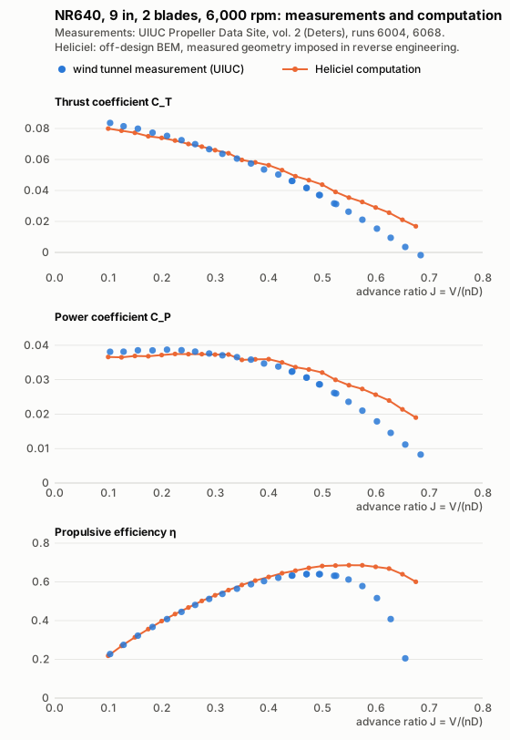 Blue dots: UIUC measurements. Orange line: Heliciel. Same propeller, same speed
Point by point, Heliciel being interpolated at the J of each measurement:
| J | Run | C_T measured | C_T Heliciel | Deviation | C_P measured | C_P Heliciel | Deviation | η measured | η Heliciel |
|---|---|---|---|---|---|---|---|---|---|
| 0.104 | 6004 | 0.0836 | 0.0798 | −4.6 % | 0.0381 | 0.0366 | −4.0 % | 0.227 | 0.226 |
| 0.129 | 6004 | 0.0814 | 0.0784 | −3.7 % | 0.0382 | 0.0366 | −4.2 % | 0.275 | 0.276 |
| 0.156 | 6004 | 0.0799 | 0.0767 | −3.9 % | 0.0385 | 0.0369 | −4.3 % | 0.323 | 0.324 |
| 0.183 | 6004 | 0.0773 | 0.0747 | −3.4 % | 0.0385 | 0.0369 | −4.1 % | 0.367 | 0.370 |
| 0.210 | 6004 | 0.0753 | 0.0733 | −2.7 % | 0.0387 | 0.0373 | −3.7 % | 0.408 | 0.413 |
| 0.237 | 6004 | 0.0725 | 0.0712 | −1.8 % | 0.0386 | 0.0374 | −2.9 % | 0.445 | 0.451 |
| 0.263 | 6004 | 0.0699 | 0.0691 | −1.1 % | 0.0382 | 0.0374 | −2.0 % | 0.481 | 0.485 |
| 0.289 | 6004 | 0.0667 | 0.0670 | 0.5 % | 0.0376 | 0.0374 | −0.7 % | 0.512 | 0.518 |
| 0.313 | 6004 | 0.0636 | 0.0649 | 2.1 % | 0.0371 | 0.0373 | 0.6 % | 0.538 | 0.546 |
| 0.341 | 6004 | 0.0606 | 0.0613 | 1.1 % | 0.0366 | 0.0363 | −0.6 % | 0.565 | 0.575 |
| 0.367 | 6004 | 0.0574 | 0.0586 | 2.1 % | 0.0358 | 0.0359 | 0.1 % | 0.588 | 0.600 |
| 0.391 | 6004 | 0.0535 | 0.0569 | 6.4 % | 0.0347 | 0.0360 | 3.7 % | 0.604 | 0.619 |
| 0.418 | 6004 | 0.0503 | 0.0540 | 7.4 % | 0.0338 | 0.0353 | 4.3 % | 0.621 | 0.640 |
| 0.443 | 6004 | 0.0461 | 0.0502 | 9.0 % | 0.0323 | 0.0340 | 5.2 % | 0.632 | 0.655 |
| 0.444 | 6068 | 0.0462 | 0.0501 | 8.5 % | 0.0324 | 0.0340 | 4.7 % | 0.632 | 0.655 |
| 0.471 | 6068 | 0.0416 | 0.0471 | 13.3 % | 0.0306 | 0.0331 | 8.1 % | 0.639 | 0.670 |
| 0.471 | 6004 | 0.0417 | 0.0471 | 12.8 % | 0.0306 | 0.0331 | 7.9 % | 0.641 | 0.670 |
| 0.494 | 6068 | 0.0371 | 0.0444 | 19.8 % | 0.0287 | 0.0323 | 12.6 % | 0.639 | 0.680 |
| 0.496 | 6004 | 0.0370 | 0.0442 | 19.6 % | 0.0286 | 0.0322 | 12.5 % | 0.640 | 0.680 |
| 0.522 | 6068 | 0.0316 | 0.0396 | 25.0 % | 0.0262 | 0.0302 | 15.4 % | 0.632 | 0.684 |
| 0.526 | 6004 | 0.0312 | 0.0389 | 24.6 % | 0.0260 | 0.0299 | 15.0 % | 0.631 | 0.685 |
| 0.549 | 6068 | 0.0263 | 0.0355 | 35.2 % | 0.0236 | 0.0284 | 20.6 % | 0.612 | 0.686 |
| 0.575 | 6068 | 0.0211 | 0.0326 | 54.2 % | 0.0210 | 0.0273 | 30.0 % | 0.578 | 0.686 |
| 0.602 | 6068 | 0.0153 | 0.0287 | 86.9 % | 0.0179 | 0.0255 | 42.5 % | 0.516 | 0.677 |
| 0.628 | 6068 | 0.0095 | 0.0251 | 165.0 % | 0.0146 | 0.0236 | 62.3 % | 0.408 | 0.666 |
| 0.655 | 6068 | 0.0035 | 0.0202 | n.s. | 0.0112 | 0.0209 | 86.7 % | 0.205 | 0.633 |
| 0.684 | 6068 | −0.0018 | 0.0055 | n.s. | 0.0083 | 0.0112 | 36.1 % | −0.148 | 0.336 |
Up to J 0.37, deviations stay between −5 and +2 % on C_T and C_P, and efficiency is matched within 0.012. The computed curve then does not bend down as fast as the measurement: at J 0.52, Heliciel gives 25 % more thrust. Thrust vanishes at nearly the same J (0.689 against 0.674). In between, the measured thrust falls along a gentle slope, whereas the computed thrust stays higher and then drops sharply over the last two points. Near zero thrust, the ratio of two small quantities makes relative deviations meaningless: they are marked n.s. when the measured C_T is below 0.005.
6: The same sweep at 3,000 rpm
At 3,000 rpm the Reynolds numbers are halved (table of section 5). Same protocol, advance speed from 1.14 to 8.0 m/s.
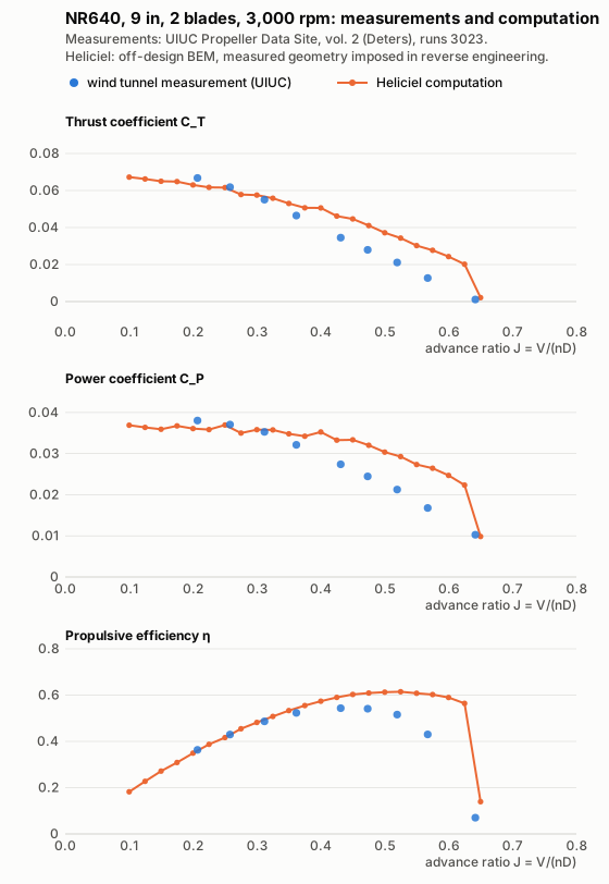 Blue dots: UIUC measurements, run 3023. Orange line: Heliciel
| J | Run | C_T measured | C_T Heliciel | Deviation | C_P measured | C_P Heliciel | Deviation | η measured | η Heliciel |
|---|---|---|---|---|---|---|---|---|---|
| 0.207 | 3023 | 0.0668 | 0.0626 | −6.3 % | 0.0380 | 0.0360 | −5.3 % | 0.363 | 0.360 |
| 0.258 | 3023 | 0.0618 | 0.0604 | −2.3 % | 0.0371 | 0.0363 | −2.0 % | 0.430 | 0.429 |
| 0.312 | 3023 | 0.0551 | 0.0567 | 3.0 % | 0.0353 | 0.0358 | 1.4 % | 0.487 | 0.494 |
| 0.362 | 3023 | 0.0465 | 0.0519 | 11.6 % | 0.0321 | 0.0345 | 7.4 % | 0.523 | 0.544 |
| 0.431 | 3023 | 0.0346 | 0.0458 | 32.6 % | 0.0274 | 0.0333 | 21.5 % | 0.544 | 0.593 |
| 0.473 | 3023 | 0.0280 | 0.0413 | 47.7 % | 0.0245 | 0.0321 | 31.3 % | 0.541 | 0.609 |
| 0.519 | 3023 | 0.0211 | 0.0349 | 65.5 % | 0.0212 | 0.0295 | 39.0 % | 0.516 | 0.614 |
| 0.567 | 3023 | 0.0127 | 0.0285 | 124.1 % | 0.0168 | 0.0267 | 59.4 % | 0.430 | 0.605 |
| 0.642 | 3023 | 0.0011 | 0.0079 | n.s. | 0.0103 | 0.0139 | 35.0 % | 0.070 | 0.367 |
Agreement holds only up to J 0.31, then the overestimate grows faster than at 6,000 rpm: +33 % on C_T at J 0.43, against +7 to +9 % between J 0.42 and 0.44 at 6,000 rpm. Heliciel reproduces the direction of the Reynolds effect: its maximum efficiency drops from 0.686 to 0.614 when the speed goes from 6,000 to 3,000 rpm. It does not reproduce its magnitude: a computed drop of 0.07, against 0.10 measured.
7: What can be said, and what remains open
What is established
- On this propeller and at these Reynolds numbers, Heliciel matches the measured C_T, C_P and efficiency within a few percent over the lower half of the sweep, where the propeller is loaded: J ≤ 0.37 at 6,000 rpm, J ≤ 0.31 at 3,000 rpm.
- Beyond that, it overestimates thrust and power, more so as J increases and as the Reynolds number drops. The computed efficiency is then too high: +0.045 at maximum efficiency at 6,000 rpm, +0.07 at 3,000 rpm.
- The computed geometry is indeed the measured one: the applied chords and pitch angles reproduce the table to the hundredth, checked element by element.
- The computation is reproducible: the 6,000 rpm sweep, run again, returned a table identical to the bit.
What remains open
- Low Reynolds polars. The elements work at Reynolds numbers between 6,000 and 46,000. The upper part of the sweep corresponds to low angles of attack, where the polars of a thin section at low Reynolds number are the most delicate, and that is where the overestimate appears. In off-design mode, Heliciel takes for each element the profile polar at the nearest Reynolds number, without interpolating between two polars. An element whose Reynolds number falls below the lowest polar of the profile therefore receives that one. This is the first lead to examine: the lowest Reynolds number and the spacing between polars of the
clarky_turbulentprofile, then a comparison with a free-transition Clark Y. - A single section for the whole blade, whereas the real thickness varies from 37 to 8 %. The blade root carries little load, but its effect is not quantified here.
- The hub radius, set at 0.155 R for lack of data.
- Off-design angles of attack are searched in whole degrees, as on the B-series; the weight of this discretization is not measured.
- The 3- and 4-blade configurations, the 5-inch model and the full-scale propeller of Report 640 remain to be run. The last one requires taking the nacelle and the effective thrust into account.
8: Reproducing this comparison
The reference data are public: files nr640_9_15deg_geom.txt (surveyed geometry), nr640_9_15deg_0782rd_6004.txt, nr640_9_15deg_0783rd_6068.txt and nr640_9_15deg_0778rd_3023.txt of volume 2 of the UIUC database. In Heliciel, the "Aircraft propeller" model is loaded and put in reverse engineering mode. Through an assistant connected to the local MCP connector, the sequence is:
charger_modele_projet, then a firstdesign_heliceat a diameter of 228.6 mm;appliquer_geometrie_relevee, which applies the 18 stations, the section and the hub, and enters reverse engineering mode;analyser_point_fonctionnementat the desired speed, thencalculer_retro_conceptiontwice;generer_courbes_analyse_multipleover advance speed, off-design mode, thenlire_tableau_analyse.
In the interface, the reverse engineering grid takes the pitch angles; the surveyed chord law is applied through the connector.
Related pages: validation on the Wageningen B-series · reverse engineering an existing propeller · Kt, Kq and J · computation method
 Global site map
 Mecaflux
 Tutorials Mecaflux Pro3D
 Tutorials Heliciel
 Tutorials Heliciel PRO CFD
 Mecaflux Store
 Compare software functions
 Quotes, Orders, Payment Methods
 project technical studies