
Thicknesses, linkages, parts list and dimensioned drawings: the Kit tab turns the computed turbine into a fabrication file.
Kaplan turbine fabrication kit: sheets, parts list and drawings
The Kit tab turns the computed turbine into a fabrication file: the parts of the 3D exploded view, developed flat, with their parts list, dimensioned drawings and STL export, as well as the guide vane linkage and the pitch variation mechanism.
Kit tab, in the right part of the window. Each block explained here carries a ? help icon in the window: clicking the icon opens the matching section of this page directly.
Contents:
Kit parameters: sheets, linkages and pitch mechanism
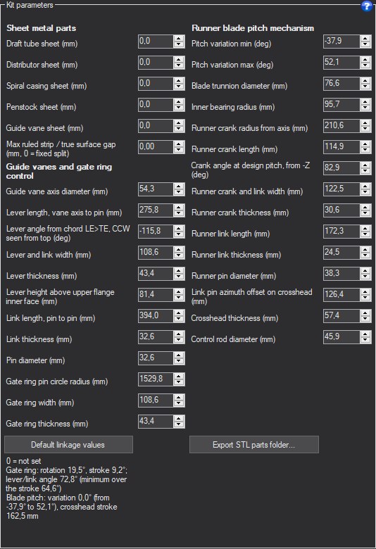
- Enter the sheet thicknesses.
- Click Default linkage values for a first set of dimensions, then adjust them.
- Export the STL parts to a folder.
- Sheet thicknesses (mm): draft tube, distributor, spiral casing, penstock, guide vane; 0 means "not set". They are also used for the shells of the 3D exploded view.
- Guide vane linkage: axis circle, levers (length, width, thickness, setting, height), links, gate ring (radius, width, thickness), joints.
- Pitch variation mechanism: runner cranks and links, spider, rod, trunnion, bearing, minimum and maximum pitch variation (°), azimuthal offset.
- Default linkage values: presetting computed on the current geometry, which replaces the dimensions after confirmation.
- Export STL parts folder: flat and formed parts, plus the parts list in CSV format.
Missing dimensions are listed under the table: the 3D view does not show a linkage that is not set.
Example
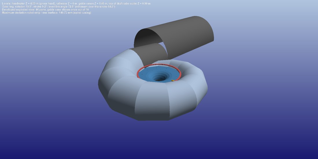
The 3D exploded view of the kit parts, with the entered thicknesses.
Parts list and detail drawings

- Choose a part in the parts list.
- Read its dimensioned drawing in the detail tab.
One row per part: mark, component, designation, quantity, flat size, developed area, thickness, deviation between ruled strip and true surface. One tab per part holds its dimensioned drawing: flat pattern, holes, or turned or machined part drawing.
The deviation between ruled strip and true surface tells how far the rolled sheet departs from the theoretical shape: beyond the allowed deviation, the part must be formed another way.
Example
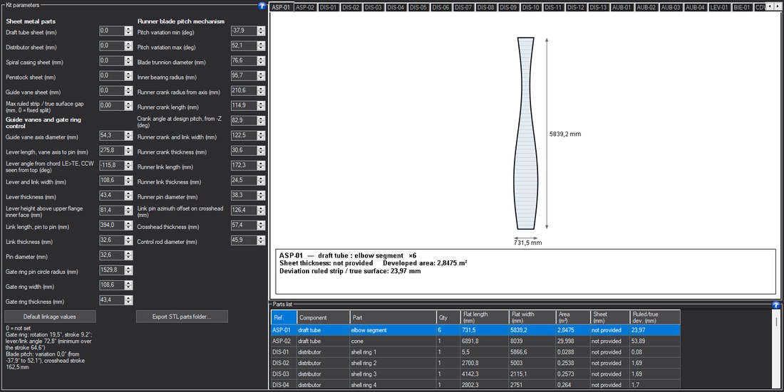
The Kit tab: dimensioned drawing of a part and parts list.
Going further
The Hydro Turbine design reference page presents the complete method and a worked case. The other help pages of the window:
 Global site map
 Mecaflux
 Tutorials Mecaflux Pro3D
 Tutorials Heliciel
 Tutorials Heliciel PRO CFD
 Mecaflux Store
 Compare software functions
 Quotes, Orders, Payment Methods
 project technical studies