
The downstream propeller is not a mirror of the upstream one: it is drawn for the rotating flow it receives. Spacing, speed and torques are set in the bench.
Contra-rotating ultralight propeller: from design to manufacturing file
The screenshots show Heliciel's French interface; the English label of each control is given in the text.
A propeller leaves behind it air that is accelerated, but also rotating: energy spent that does not push. A second propeller placed behind it, turning the other way, can take that rotation back and add its thrust, without enlarging the diameter. This case study splits the propeller of the ultralight tutorial (in French): 1,700 mm, 3 blades, 1,137.5 rpm, designed for 130 km/h (36.1 m/s).
- Tutorial steps:
- Open the contra-rotating project
- The pair: what the downstream propeller receives
- The spacing between the propellers
- Downstream propeller speed and torques
- Seeing the flow
- Reading the recovered rotation
- Exporting both blades
1: Open the contra-rotating project
With the ultralight propeller open, menu Files > Contra Rotative project. The function requires a propulsion propeller: on a wind turbine or a tidal turbine Heliciel refuses and says so — "Contra rotative function is only for propulsive props."
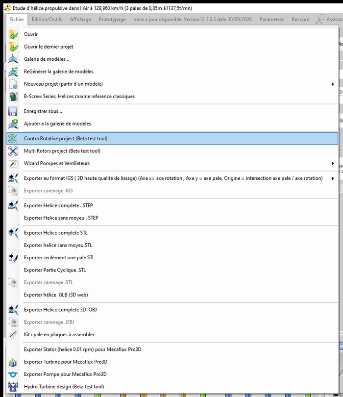
The menu entry, just above the multirotor project
The window is the multirotor bench, in the Contra Rotative (no frame) family: a single pair, no arms, no modules, no pitch study — the pitch group stays inactive, and only ducts, if any, create drag.
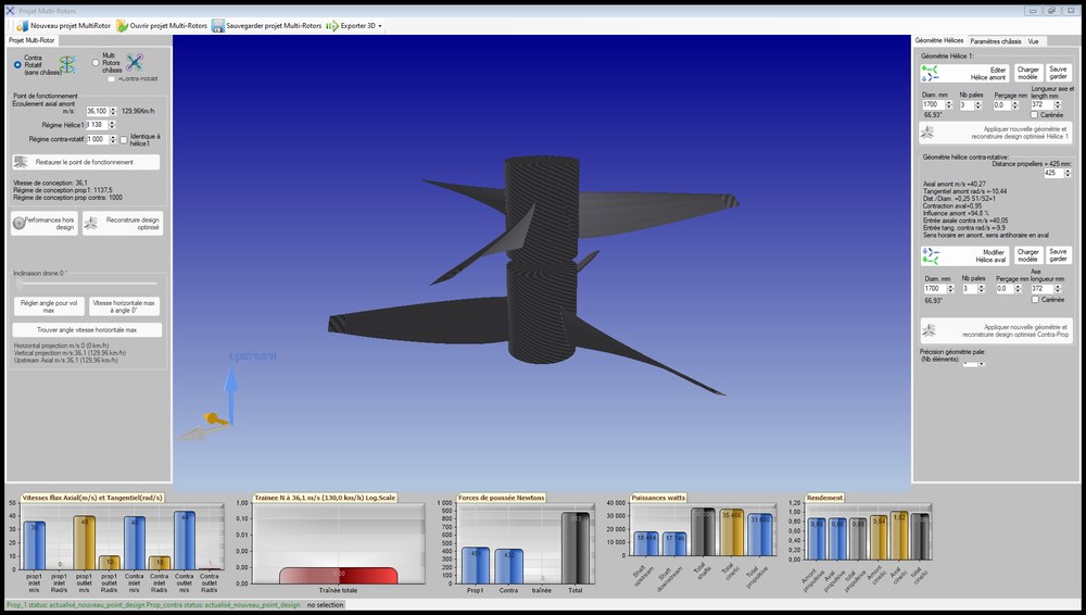
The contra-rotating project: one pair, no frame
2: The pair: what the downstream propeller receives
On rebuild, Heliciel keeps the project's propeller as the upstream propeller, then designs the downstream propeller for the flow the upstream one leaves it: faster, and rotating. Same diameter, same speed to start with:
- Single propeller (reference): 451 N, 18.5 kW, propulsive efficiency 0.882, exit rotation 10.4 rad/s
- Upstream propeller of the pair: 451 N, 18.5 kW — it is the same one
- Flow received by the downstream propeller: 40.05 m/s and −9.9 rad/s (rotation opposite to its own)
- Downstream propeller: 577 N, 24.3 kW
- Pair: 1,028 N for 42.8 kW, propulsive efficiency 0.867, exit rotation 2.0 rad/s
For the same diameter, the pair pushes 2.3 times more than the single propeller, for 2.3 times the power: efficiency loses a point and a half (0.867 against 0.882), and the rotation left in the wake falls from 10.4 to 2.0 rad/s. The downstream propeller, although of the same diameter, has its own twist: Edit Downstream Proppeller opens it in the designer.
3: The spacing between the propellers
In this project type only, the distance between the two propeller planes can be entered (in a multirotor it is deduced from the frame). The ContraRotative propeller geometry group then displays the x/D ratio, the influence factor — the share of the upstream wake that reaches the downstream propeller, from a law after Rebuffet corrected for the stream-tube contraction — and the transmitted flow. Each spacing needs a rebuild: the downstream propeller is redrawn for its new flow.
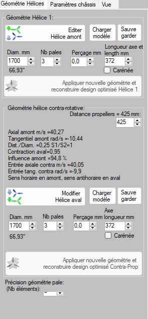
425 mm spacing: x/D 0.25, influence 94.8%
| Spacing | x/D | Influence factor | Flow received downstream | Downstream thrust | Downstream power | Total thrust | Exit rotation | Propulsive efficiency |
|---|---|---|---|---|---|---|---|---|
| 100 mm | 0.06 | 0.77 | 39.30 m/s, −8.0 rad/s | 560 N | 23.5 kW | 1,011 N | 3.7 rad/s | 0.870 |
| 425 mm | 0.25 | 0.95 | 40.05 m/s, −9.9 rad/s | 577 N | 24.3 kW | 1,028 N | 2.0 rad/s | 0.867 |
| 850 mm | 0.50 | 0.93 | 39.99 m/s, −9.8 rad/s | 576 N | 24.3 kW | 1,027 N | 2.2 rad/s | 0.868 |
| 1,700 mm | 1.00 | 0.55 | 38.39 m/s, −5.7 rad/s | 497 N | 20.6 kW | 948 N | 5.3 rad/s | 0.876 |
Upstream propeller unchanged in every case: 451 N, 18.5 kW. Propulsive efficiency of the pair = total thrust × 36.1 m/s / total shaft power.
- Too close (100 mm): the wake has not yet reached its speed, the downstream propeller receives less of it (factor 0.77);
- too far (1,700 mm): the wake has dissipated (factor 0.55), the downstream propeller pushes less and leaves more rotation;
- between x/D = 0.25 and 0.5 the influence is at its highest: that is the range where the pair works best together.
4: Downstream propeller speed and torques
At equal speed, the downstream propeller absorbs more torque than the upstream one: 204.2 N·m against 155.0. The difference, 49.2 N·m, is still passed on to the airframe — precisely what contra-rotation aims to cancel. Untick Same as propeller1, set the downstream speed, then Apply new geometry and rebuild optimized design Contra-Prop:
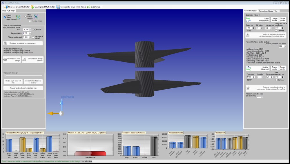
Downstream speed 1,000 rpm, 425 mm spacing
- Downstream speed: 1,000 rpm (upstream 1,137.5)
- Downstream propeller: 432 N, 17.7 kW, torque 169.5 N·m
- Torque difference between the propellers: 14.5 N·m (against 49.2 at equal speed)
- Pair: 883 N for 36.2 kW, propulsive efficiency 0.880
- Exit rotation: 1.0 rad/s
Slowing the downstream propeller brings the two torques closer, recovers even more rotation, and brings the efficiency back to that of the single propeller (0.880 against 0.882) — at the cost of a lower total thrust (883 against 1,028 N). The right setting depends on what you are after: maximum thrust, or a machine without reaction torque.
5: Seeing the flow
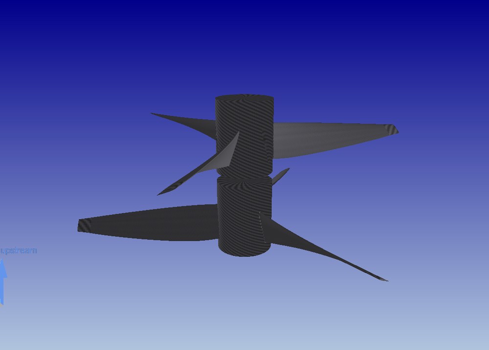
The pair in perspective: upstream propeller at the top, facing the incoming flow
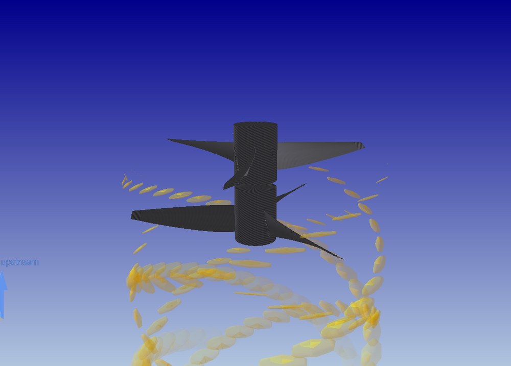
Tip vortices, upstream and downstream (Tip vortex boxes of both particle groups)
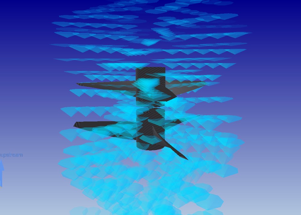
Induced speed particles of both stages
6: Reading the recovered rotation
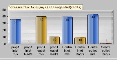
Speeds: entry and exit of each propeller
The axial and tangential flow speeds chart reads from left to right, in the direction of the air: the upstream propeller (prop1) receives 36 m/s without rotation and returns 40 m/s with 10 rad/s; the downstream propeller (Contra) receives that flow and returns 44 m/s with only 1 rad/s. The red bar on the right, almost zero, is the rotation that remains: the downstream propeller took the rest back.
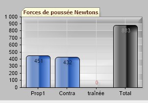
Forces: 451 N upstream, 432 N downstream, 883 N in total
7: Exporting both blades
Toolbar, Export 3D: both blades, each in its own direction — the interface reminds you,
"Upstream ClockWise, Downstream CounterClockWise". Here, the upstream blade in right-hand STL (printing),
the downstream blade in left-hand IGES (CAD). The project is saved in the .mlrot format.
Going further: the coaxial X8: the same physics on a drone, the contra-rotating pair overview, the theory of contra-rotating propellers.
 Global site map
 Mecaflux
 Tutorials Mecaflux Pro3D
 Tutorials Heliciel
 Mecaflux Store
 Compare software functions
 Quotes, Orders, Payment Methods
 project technical studies