
The five pictures the CFD bench produces, and what each one says about your machine. Ten minutes of reading.
Understanding a CFD result in five pictures
You design systems with propellers, fans or wings, and you are not a specialist in computational fluid dynamics. This page is written for you. The CFD (Computational Fluid Dynamics, the numerical simulation of the flow) bench of Heliciel PRO always produces the same five pictures, whatever the machine. Once you can read them, every case study in this collection can be read at a glance.
First, the principle in one sentence: the Heliciel designer computes your machine slice by slice, quickly and well, with the blade element method (BEM); the CFD bench then fills the whole space around it with small cells of air or water and solves the flow in each one. The first gives the design figures; the second checks them and shows the fluid. There is nothing to set: a mesh preset to pick from a list, two buttons, and the bench does the rest.
CFD result, picture 1: pressure on the skin
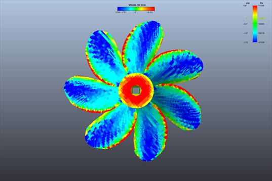
A boat propeller seen from upstream. Blue: the fluid pulls. Red: the fluid pushes. Green: nothing happens.
This is the most telling picture. Every point of the blade is coloured by the pressure the fluid exerts on it. A working blade is blue on one side and red on the other: the difference makes the thrust. The red hub nose is the stagnation point, where the fluid hits head-on. Two habits for reading it: untick 3D model so that the grey shape does not cover the colours, and read the scale on the right, in pascals: its minimum is the lowest pressure of the computation, the one that decides cavitation in water.
Picture 2: streamlines
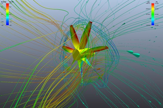
An aircraft propeller at static thrust: air comes from everywhere and leaves as a jet.
Each line is the path of a fluid particle, coloured by its speed. They tell where the fluid comes from and where it goes: straight and parallel around a healthy wing, narrowing behind a propeller that pushes, widening behind a wind turbine that brakes, curling where the flow separates. This is the picture that answers "what does the fluid do around my machine?".
Picture 3: the cut
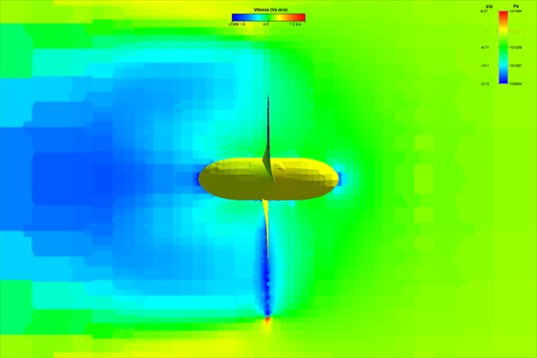
The wind, cut in a vertical plane, around a wind turbine: it slows down (blue) as it crosses the rotor.
The cut colours the fluid itself in a plane of your choice: vertical along the axis to see the jet or the wake, perpendicular to the axis to see the section of the stream tube, cylindrical to follow the blade at a given radius. It shows velocity or pressure. This is the picture of orders of magnitude: how much the fluid accelerates, how far the wake extends, where the pressure jumps. A click on the cut gives the exact value at the clicked point.
Picture 4: the cross cut
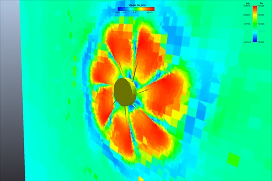
Behind a rotating 7-blade propeller: the footprint of each blade in the air.
The same tool, in a plane perpendicular to the axis. It shows what a side view hides: the active ring of the blades, the slow core behind the hub, and on a real-rotation computation, the footprint of each blade. This is the picture that says whether the fluid works evenly over the disc or whether part of the blade is doing nothing.
CFD result, picture 5: the results panel
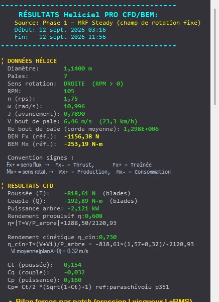
The results panel of a boat propeller: the designer's reference at the top, the forces computed by CFD below.
Not a picture, but this is where you end up. The panel gives the forces on the blades, the shaft power, the efficiency, and recalls just above what the designer had announced. The gap between the two is the real result of the computation. Three habits to take up:
- Read the alerts first. The bench writes on its own when a quantity is not reliable, for instance "torque not reliable" on a lightly loaded wind turbine. An alert does not invalidate the computation, it says which line not to take at face value.
- Axial forces are robust, torques are fragile. Thrust, traction and lift are sums over the whole surface: they move little from one mesh to another. The torque of a lightly loaded machine is a small difference between two large terms and needs a fine mesh.
- A gap with the designer is not an error. On a wide-blade propeller, CFD sees the blades interfering with each other and finds less; on a fan behind an obstacle, it sees the installation and finds something else. The gap is information about your machine.
The two phases of the computation, in two lines
For a propeller, the bench chains two computations. The first freezes the propeller and simulates the rotation: fast, it gives the mean forces and all the pictures above. The second really rotates the propeller: longer, it adds the fluctuation of the forces at each blade passage, the one that vibrates and can be heard, and it is indispensable when nothing comes from upstream, as at static thrust. The bench chains both if you ask it to, and stops on its own when the forces are stable.
What now
Each case study in the collection applies this reading to a real machine, computed from start to finish: a boat propeller and its cavitation, an aircraft propeller in cruise and at static thrust, a wind turbine and a tidal turbine, two fans with their installation, a wing. Start with the machine that looks like yours.
The CFD case studies
Next: Boat propeller CFD: thrust and pressure on the blades »
- Understanding a CFD result in five pictures (you are here)
- Boat propeller CFD: thrust and pressure on the blades
- Aircraft propeller CFD: cruise and static thrust
- Drone propeller CFD: hover
- Wind turbine CFD: power and wake
- Tidal turbine CFD: a 16 m rotor in the current
- Ducted fan CFD: duct and radiator
- Wing CFD and hydrofoil: lift and drag
These case studies complement the Heliciel design tutorials (in French), which cover the BEM side: blade design, choice of speed, performance curves. To go further into the method, the technical collection of twenty tutorials remains available.
 Global site map
 Mecaflux
 Tutorials Mecaflux Pro3D
 Tutorials Heliciel
 Mecaflux Store
 Compare software functions
 Quotes, Orders, Payment Methods
 project technical studies