
Two solvers, four sizing functions and the opening slider: everything that drives the turbine sits in the left panel.
Kaplan turbine solver and sizing: the control panel
The left panel of Hydro Turbine design stays visible whatever tab is open. It holds the commands that act on the whole machine: the two solvers that balance the runner on the site head, the functions that set a dimension from a recognised rule, and the distributor opening slider, which sets the flow.
Left panel of the Hydro Turbine design window (menu File > Hydro Turbine design). From bottom to top, the three blocks are: Propeller solver, AutoSizing functions, Distributor open at … °. Each block explained here carries a ? help icon in the window: clicking the icon opens the matching section of this page directly.
Contents:
- Solver: a runner that absorbs exactly the available head
- AutoSizing functions: D, hub, b0 and rpm in one click
- Distributor opening: setting the guide vanes and reading the flow
Solver: a runner that absorbs exactly the available head
- Enter the site (Layout tab) and choose the rpm (Turbine type tab).
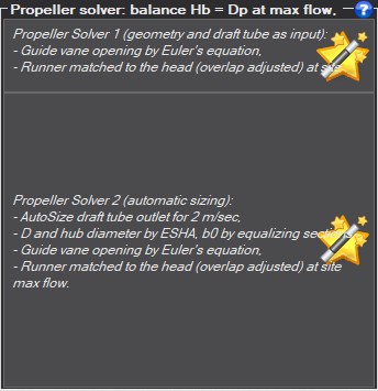
- Click Solver 2 for a complete first sizing, or Solver 1 to keep the input geometry.
- Wait for the runner computations to finish, then read the Errors tab: it must be empty.
- Read the balance in the Results tab: runner head plus losses must give back the gross head.
A propeller or Kaplan turbine in a penstock is right only if the head absorbed by the runner, added to the losses of the whole water path, gives back the gross head of the site: Hb = path losses + runner head, at the maximum site flow. The solver finds this balance for you. Two buttons, two levels of automation.
Solver 1, input geometry and draft tube. Your dimensions are kept: runner diameter D, hub, guide vane height b0, draft tube. The solver:
- opens the guide vanes by Euler's equation: it targets the angular momentum K = g·(Hb − losses at this opening) / ω and finds it by bisection on the opening slider;
- adjusts the blade overlap until the runner absorbs the available head.
If the Euler target cannot be reached, it stops with a message: the geometry has to be revised.
Solver 2, automatic sizing. It sizes first, then balances: draft tube computed for the target outlet velocity at maximum flow (2 m/s by default, adjustable in the Draft tube tab), D and hub from the ESHA formulas, b0 by equalizing the distributor and runner sections, Euler opening with remedies if the target cannot be reached (b0, then guide vane axis circle), and finally the overlap.
What the solver does not do. If the head is not enough for the minimum overlap, the rpm is reduced. Cavitation is judged after balancing, along the water path and on the blades, the blades being set at the runner outlet pressure: it is information, no automatic correction is made. During balancing, the blade cavitation test is disabled, because it would prevent convergence.
Good practice. Start with Solver 2 for a first draft, then change one dimension and run Solver 1: it keeps your choices. Always read the Errors tab before the results.
Examples

After balancing: the gross head shared between the path losses and the runner head (left), the powers (centre), the efficiencies (right).
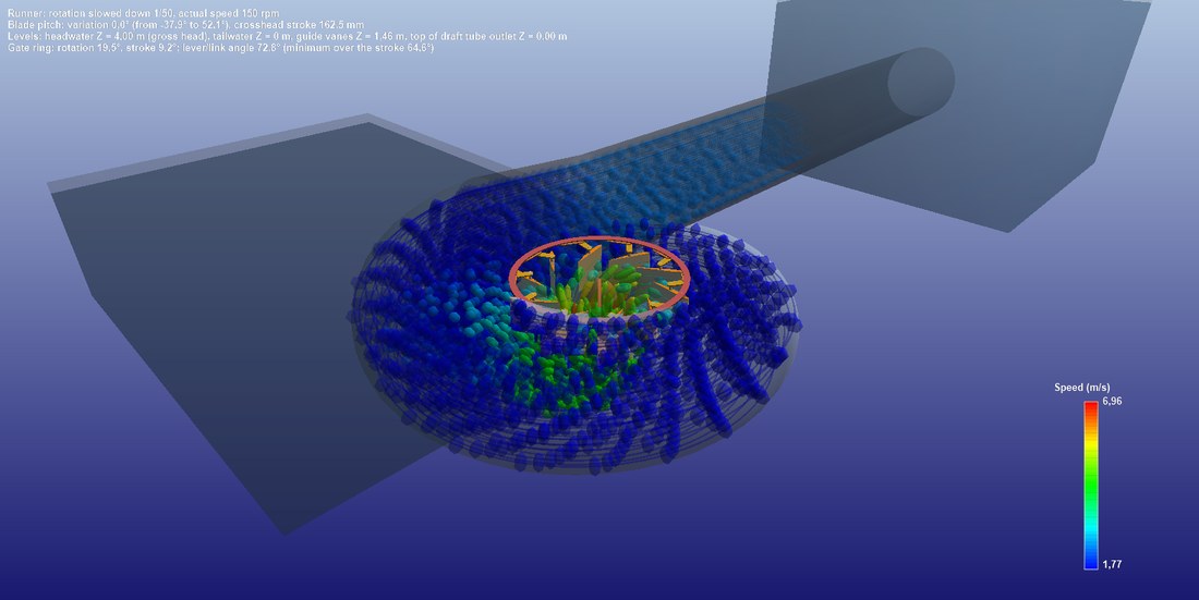
The balanced turbine in 3D: the water trajectories flow through the computed runner.
AutoSizing functions: D, hub, b0 and rpm in one click
- First set the test rpm so that the specific speed falls in the Kaplan range.
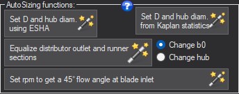
- Click Set D and hub diam. using ESHA (or from Kaplan statistics).
- Choose Change b0 or Change hub, then click Equalize distributor outlet and runner sections.
- Check the resulting geometry in the vertical view, then balance with a solver.
These buttons set one or two dimensions from a recognised rule, without running the balancing. They build a starting geometry, or test the effect of a rule.
- Set D and hub diam. using ESHA: D = 84.5·(0.79 + 1.602·NQe)·√H / N and d = (0.25 + 0.0951 / NQe)·D, from the small hydropower guide of ESHA (European Small Hydropower Association); the hub formula is due to Lugaresi and Massa. NQe is the specific speed of the "Turbine type" tab.
- Set D and hub diam. from Kaplan statistics: read on the similitude curves of the "Propeller-Kaplan statistics" tab (A. Tenot reference) for the current specific speed.
- Equalize distributor outlet and runner sections: the passage area under the guide vanes, b0·π·D, is made equal to the ring swept by the runner, π·(D² − d²)/4. The radio button selects the modified quantity: Change b0 (hub kept) or Change hub (b0 kept), D staying fixed. Equal sections avoid accelerating or slowing the water between the two components.
- Set rpm to get a 45° flow angle at blade inlet: adjusts the rpm so that the axial and tangential velocities, distributor swirl included, give 45° at the runner inlet.
These functions do not guarantee the head balance: finish with a solver.
Example
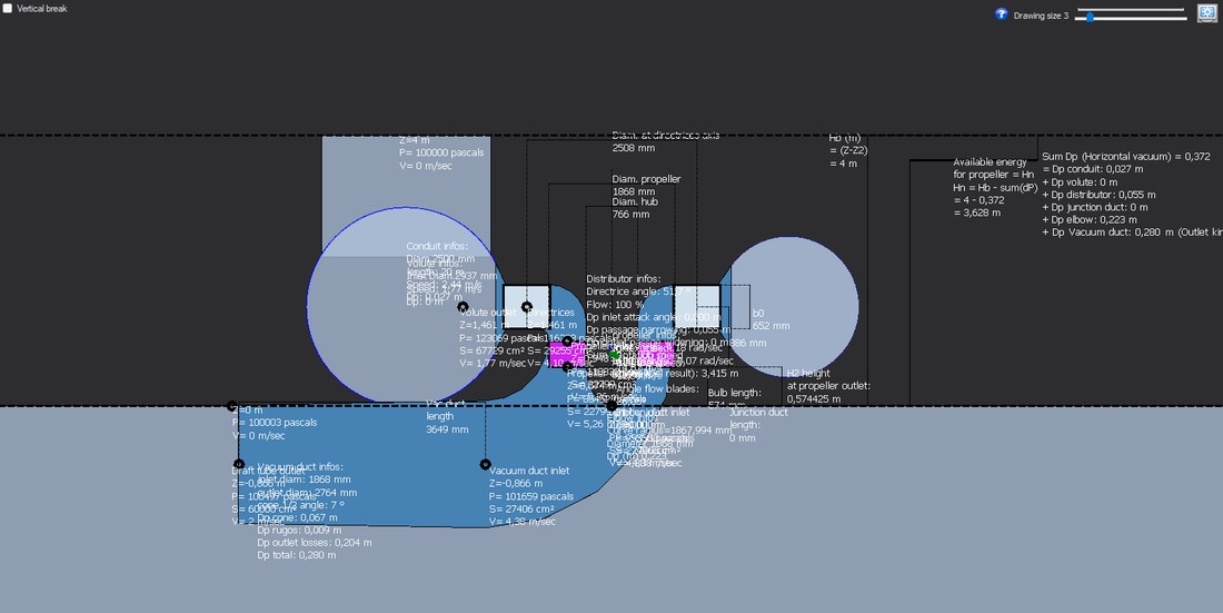
The dimensioned vertical view after sizing: runner diameter, hub and guide vane height b0.
Distributor opening: setting the guide vanes and reading the flow
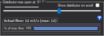
- Move the slider: the block title shows the guide vane opening.
- Tick Show distributor on scroll to see the guide vanes turn in the top view.
- Read the resulting flow in the gauge, in m³/s and as a percentage of the maximum flow.
- Run a solver again to return to the balanced opening.
The block title shows the current guide vane opening angle ("Distributor open at … °"). The slider sets this opening to a tenth of a degree; the gauge shows the current flow in m³/s and as a percentage of the maximum site flow. This is the control member of a real turbine: the flow is not an input, it results from the opening.
Show distributor on scroll: when ticked, the window switches to the top view while you move the slider, so you see the guide vanes turn and the passage open.
The solvers move this slider themselves (opening by Euler's equation). An opening different from the one found by the solver unbalances the runner: this is how the turbine is studied at part load.
Examples

The guide vanes in 3D, seen from above, at 20°, 35° and at maximum opening: the passage between vanes opens and the flow increases.
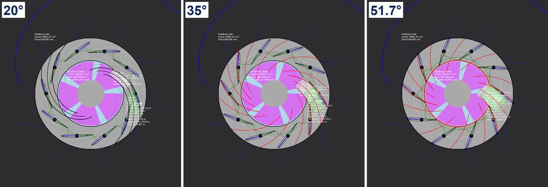
The same openings in the 2D top view, with the guide vane passage details.
Going further
The Hydro Turbine design reference page presents the complete method and a worked case. The other help pages of the window:
 Global site map
 Mecaflux
 Tutorials Mecaflux Pro3D
 Tutorials Heliciel
 Tutorials Heliciel PRO CFD
 Mecaflux Store
 Compare software functions
 Quotes, Orders, Payment Methods
 project technical studies