
In flight at 200 km/h, then at full power with the aircraft standing still: two flows with nothing in common.
Aircraft propeller CFD: the same propeller simulated in cruise and at static thrust
An aircraft propeller lives two lives, and CFD shows them both. In cruise, it works in a 200 km/h wind that it only accelerates slightly. At take-off, brakes on, it must draw in still air and throw it backwards. The Heliciel designer sizes it for cruise; this case study shows, with the CFD (Computational Fluid Dynamics, numerical simulation of the flow) bench, what it really does in both situations. The pictures almost speak for themselves.
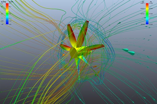
At static thrust, the propeller draws air from everywhere: the streamlines arrive from the side, from behind, curl around and leave as a concentrated jet. A picture impossible to obtain other than by CFD.
- Contents:
- The propeller and its two operating points
- The aircraft propeller in CFD in cruise: an almost uniform flow
- The aircraft propeller in CFD at static thrust: suction and jet
- The forces, compared with the designer
- What the computation sees: the blade mesh
- Take-aways
1: The propeller and its two operating points
| Diameter | 1,800 mm, hub ∅ 306 mm, 7 blades |
| Speed | 1,000 rpm in both cases |
| Air | 1.012 kg/m³ (moderate altitude) |
| Blade tip speed | 94 m/s from rotation alone; 110 m/s in cruise, wind included (Mach 0.32) |
| Case 1 — cruise | aircraft at 56 m/s (202 km/h) |
| Case 2 — static thrust | aircraft standing still (0 m/s) |
The Heliciel designer, through its blade element method (BEM), announces for the same propeller: 1,186 N of traction in cruise for 805 N·m of torque, and 1,105 N at static thrust for 895 N·m. Almost the same traction, but more torque when standing still: the blade, drawn for cruise, works at too high an incidence when the aircraft is not moving.
2: The aircraft propeller in CFD in cruise: an almost uniform flow
The cruise case was meshed with the Level 5 preset (394,000 cells, 21 minutes) and computed in 1 min 51. Here is what the bench shows:
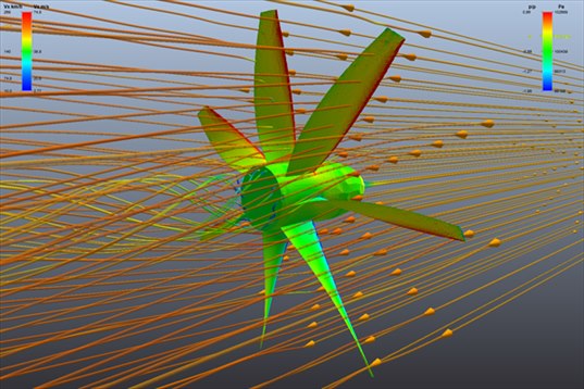
In cruise, the streamlines cross the propeller almost straight: the aircraft moves at 56 m/s, the propeller only adds a few metres per second. The leading edges are red (overpressure), the rest of the blades green-yellow.
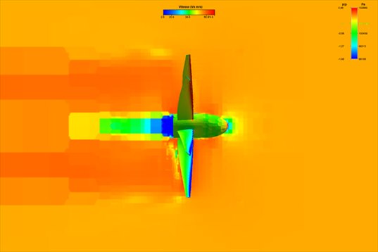
Vertical velocity cut, seen from the side. The uniform orange is the 56 m/s wind filling the whole domain. The only visible mark is the hub wake, in blue-green: the air slowed behind the propeller nose. The blade jet exists but drowns in the wind.
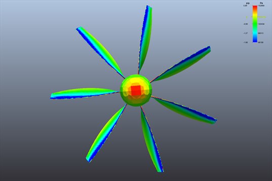
Seen from the front of the aircraft. The back of the blades is blue, in suction: this is the face that pulls. The hub nose is red: the air hits it at 56 m/s.
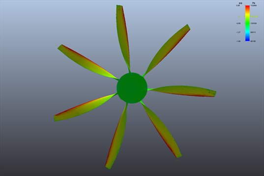
Seen from behind. The pushing face is green-yellow, with a red border along the leading edge. Little contrast: in cruise the blade is lightly loaded, as it should be.
3: The aircraft propeller in CFD at static thrust: suction and jet
Same propeller, same speed, aircraft standing still. The computation was run with the Level 3 preset (177,000 cells, 10 minutes of meshing), this time with both phases: the frozen propeller first (1 min 18), then the really rotating propeller (18 minutes). Static thrust is a difficult flow: nothing comes from upstream, everything is created by the propeller.
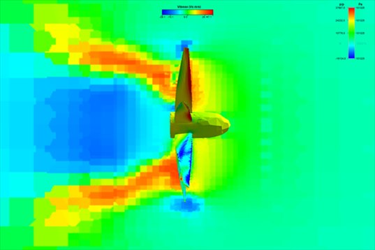
Vertical velocity cut at static thrust. This time the field is green (air at rest) and the propeller carves two structures into it: a red annular jet at more than 20 m/s behind the blades, and in the centre a wide blue zone where the air comes back towards the propeller. This is the recirculation a ground run also produces: the ejected air goes round and gets drawn in again.
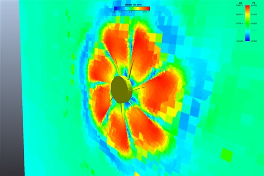
Cut perpendicular to the shaft, just behind the propeller, at one instant of the real rotation. One reads the footprint of the seven blades: seven red patches of thrown air, separated by slower zones. A picture of a rotating propeller, not of a frozen one.
4: The forces, compared with the designer
| Cruise 56 m/s | Static thrust | |
|---|---|---|
| Traction, designer (BEM) | 1,186 N | 1,105 N |
| Traction, CFD frozen propeller | 792 N (−33 %) | 1,001 N (−9 %) |
| Traction, CFD rotating propeller (mean) | — | 820 N (−26 %) |
| Torque, designer (BEM) | 805 N·m | 895 N·m |
| Torque, CFD frozen propeller | 630 N·m (−22 %) | 798 N·m (−11 %) |
| Shaft power, CFD | 66 kW | 84 kW |
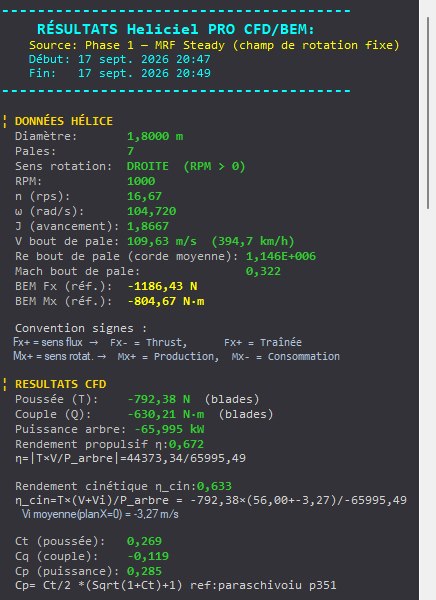
The results panel of the cruise case: 792 N on the blades, 630 N·m, 66 kW at the shaft, propulsive efficiency 0.67. Above it, the designer's reference.
Three useful readings for the design office:
- In cruise, CFD finds a third less traction than the designer, as on the boat propeller of the previous case. Seven wide blades interfere with each other, the classical method does not see it. The propulsive efficiency computed by CFD is 0.67.
- At static thrust, the absorbed power climbs: 84 kW against 66 in cruise, for a traction that does not rise. This is the expected behaviour of a fixed-pitch propeller drawn for cruise, and this is why engine power at take-off is read on the torque curve, not on the traction.
- At static thrust, the second phase is needed. The frozen propeller gives 1,001 N, the rotating propeller 820 N on average, with a fluctuation of 60 N. Without upstream flow, the first phase struggles to settle: the bench said so itself at the end of the run. The value to keep is that of the real rotation.
The second phase also gives the rhythm of the propeller: 116.7 Hz of blade passing frequency (7 blades at 16.7 revolutions per second), and this time the passing line dominates the broadband noise by 2.4 dB, whereas it stayed 12 dB below on the boat propeller. An aircraft propeller at static thrust is a noisy machine, and the computation says so.
5: What the computation sees: the blade mesh
A tick box shows the mesh covering the blade. There is nothing to set, but it is worth looking at once to understand what "Level 5" means.
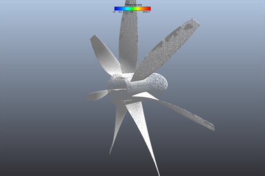
The skin mesh at the Level 5 preset: the cells tighten on the leading edges, trailing edges and hub, where the air changes direction quickly. The middle of the blade, calmer, is meshed more coarsely. The preset decides all of this.
6: Take-aways
- Two regimes, two flows: in cruise the propeller barely disturbs the wind, at static thrust it manufactures the whole flow, suction and jet included. The velocity cuts show it at a glance.
- Static thrust requires real rotation. The first phase is enough in cruise; standing still, it is the second one that gives the usable value.
- CFD is harsher than the designer on this 7 wide-blade propeller: −33 % traction in cruise. Shaft power at take-off (84 kW) is the figure that sizes the engine.
- Durations: 23 minutes for the cruise case, half an hour for static thrust with its two phases, on a 6-core desktop PC.
The CFD case studies
« Previous: Boat propeller CFD: thrust and pressure on the blades | Next: Drone propeller CFD: hover »
- Understanding a CFD result in five pictures
- Boat propeller CFD: thrust and pressure on the blades
- Aircraft propeller CFD: cruise and static thrust (you are here)
- Drone propeller CFD: hover
- Wind turbine CFD: power and wake
- Tidal turbine CFD: a 16 m rotor in the current
- Ducted fan CFD: duct and radiator
- Wing CFD and hydrofoil: lift and drag
These case studies complement the Heliciel design tutorials (in French), which cover the BEM side: blade design, choice of speed, performance curves. To go further into the method, the technical collection of twenty tutorials remains available.
 Global site map
 Mecaflux
 Tutorials Mecaflux Pro3D
 Tutorials Heliciel
 Mecaflux Store
 Compare software functions
 Quotes, Orders, Payment Methods
 project technical studies