
The smallest machine of the collection, and the fastest computation: from model to result in six minutes.
Drone propeller CFD: six minutes of simulation for a 5-inch propeller in hover
A drone propeller in CFD is a small machine that spins very fast: 127 mm in diameter, 25,000 rpm, a blade tip at half the speed of sound. It works in hover, that is in still air that it must draw in and throw downwards. This case study was created and computed from start to finish while this page was being written, from the drone model shipped with Heliciel: six minutes between loading the model and the result of the real rotation. It is the fastest case of the collection, and it shows that CFD (Computational Fluid Dynamics, numerical simulation of the flow) is not reserved for large machines.
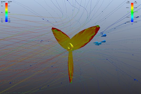
The three-blade propeller seen in perspective, pressure on the blades and streamlines. The red of the leading edges and blade tips marks the overpressure; the streamlines, coloured by speed, converge from the whole space towards the rotor disc.
- Contents:
- The machine, from designer to bench
- CFD simulation of the drone propeller: six minutes, two phases
- The jet under the rotor
- Thrust, torque, power: what the drone propeller CFD says
- The whistle: 1,250 Hz
- Take-aways
1: The machine, from designer to bench
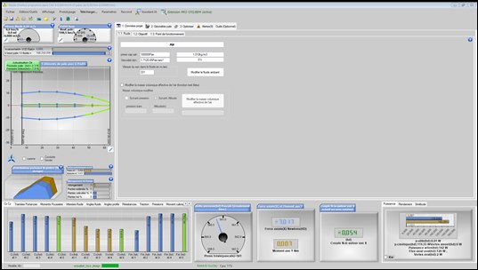
The Heliciel designer with the drone model loaded: the blade geometry on the left, the results of the classical calculation at the bottom. The PRO CFD menu sends this propeller to the bench as it is.
| Propeller | 3 blades, diameter 127 mm (5 inches), hub ∅ 14 mm, mean chord 19 mm |
| Speed | 25,000 rpm — 166 m/s at the blade tip, Mach 0.50 |
| Flight | hover (zero forward speed), air at 1.012 kg/m³ |
| Heliciel designer (BEM) | 7.02 N of thrust (716 g), 0.054 N·m, 143 W at the shaft, figure of merit 0.81 |
In hover, propulsive efficiency is meaningless (the propeller does not move forward): the designer gives instead the figure of merit, which compares the thrust obtained with the power spent. 0.81 is a good value for a propeller of this size.
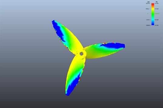
The propeller seen from above, the side where it draws in air. The back of the blades is in suction, from yellow to blue towards the blade tips, where the speed is highest. This is the face that makes most of the thrust.
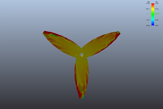
The propeller seen from below, the side where it pushes the air. The whole face is in overpressure, orange to red on the leading edges.
2: CFD simulation of the drone propeller: six minutes, two phases
| Step | Duration | What happens |
|---|---|---|
| Meshing, Level 3 preset | 1 min 39 | 53,000 cells around the propeller |
| Phase 1, frozen propeller | 38 s | mean forces, settled after 207 iterations |
| Phase 2, rotating propeller | 3 min 23 | 0.8 revolution simulated, 5,160 time steps, forces settled |
| Total | 5 min 40 | on a 6-core desktop PC, 11 processes |
Nothing was set: the mesh preset, then the two tick boxes that chain the computation after the mesh and the second phase after the first. The small size of the propeller changes nothing to the number of cells: the bench fits the domain to the machine. What changes is the time step of the real rotation, nine millionths of a second, imposed by the 416 revolutions per second: 5,160 steps for less than one revolution. The bench set it on its own.
3: The jet under the rotor
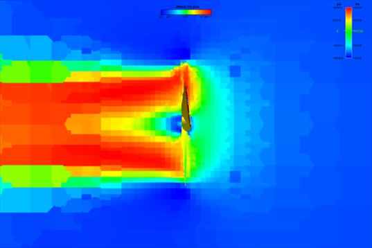
Vertical velocity cut, the propeller seen from the side, axis horizontal on the picture (in flight, this jet points downwards). On the right, the ambient air at rest (blue) is drawn in and accelerates as it approaches the rotor (green, yellow); on the left, the red jet leaves at more than 20 m/s, with a slower core in the shadow of the hub. The jet stays concentrated over several diameters.
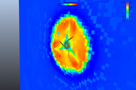
The same velocity in a plane perpendicular to the axis, just behind the propeller: the jet disc, in orange, cut into three sectors by the blade footprints. Around it, the air at rest.
The designer had predicted a mean jet speed of 31 m/s; the cut shows a slightly slower and above all non-uniform jet: fast under the blades, slow under the hub. This is exactly the information needed by whoever places a sensor, an antenna or a drone arm under the propeller.
4: Thrust, torque, power: what the drone propeller CFD says
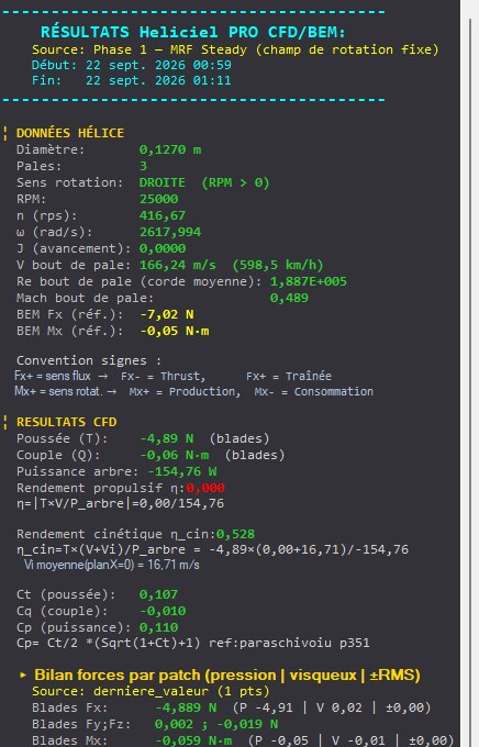
The results panel after the first phase: 4.88 N of thrust on the blades, 0.059 N·m of torque. The designer's reference is recalled above.
| Thrust | Torque | |
|---|---|---|
| Heliciel designer (BEM) | 7.02 N | 0.0543 N·m |
| CFD, frozen propeller | 4.88 N (−30 %) | 0.0591 N·m (+9 %) |
| CFD, rotating propeller (mean) | 4.94 N (−30 %) | 0.0597 N·m (+10 %) |
The two phases agree with each other, and both find 30 % less thrust than the designer for 10 % more torque. For the drone builder, the reading is direct: the available lift per motor is closer to 500 g than to 716 g, and the motor draws a little more than planned. The bench itself flags the probable cause in its alerts: on a blade with a 19 mm chord, "a laminar region is probable on the front of the profile", which the turbulence model used does not represent. A drone propeller is a small machine at a low Reynolds number, and this is the domain where the two methods agree least; the test bench remains the final judge, and CFD says on which side to stand.
5: The whistle: 1,250 Hz
The real rotation gives the blade passing frequency: 3 blades at 416.7 revolutions per second, i.e. 1,250 Hz, a high-pitched whistle, with its harmonics at 2,500, 3,750 Hz and beyond. The bench measures the fluctuation of the thrust at this frequency: 0.38 N of rms amplitude on 4.9 N, i.e. 8 % of the thrust pulsing. A small, fast, lightly loaded propeller is a machine that vibrates more than large ones. The passing line stays here 6.6 dB below the broadband noise: the pure whistle is not dominant, the rush of air prevails.
6: Take-aways
- Six minutes from model to the result of the real rotation: the CFD of a small propeller fits between two bench tests.
- −30 % thrust, +10 % torque compared with the designer, confirmed by both phases: count 500 g per motor rather than 716.
- The jet is not uniform: fast under the blades, slow under the hub. To be looked at before placing anything under the propeller.
- 1,250 Hz and 8 % of pulsing thrust: CFD gives the frequency and the amplitude to compare between two candidate propellers.
The CFD case studies
« Previous: Aircraft propeller CFD: cruise and static thrust | Next: Wind turbine CFD: power and wake »
- Understanding a CFD result in five pictures
- Boat propeller CFD: thrust and pressure on the blades
- Aircraft propeller CFD: cruise and static thrust
- Drone propeller CFD: hover (you are here)
- Wind turbine CFD: power and wake
- Tidal turbine CFD: a 16 m rotor in the current
- Ducted fan CFD: duct and radiator
- Wing CFD and hydrofoil: lift and drag
These case studies complement the Heliciel design tutorials (in French), which cover the BEM side: blade design, choice of speed, performance curves. To go further into the method, the technical collection of twenty tutorials remains available.
 Global site map
 Mecaflux
 Tutorials Mecaflux Pro3D
 Tutorials Heliciel
 Mecaflux Store
 Compare software functions
 Quotes, Orders, Payment Methods
 project technical studies