
Propeller geometry: the vocabulary to describe it
A propeller's geometry is described with three references, the rotation axis, the blade axis and the plane of rotation, and a few quantities: radius, chord, pitch angle, pitch and generatrix. This vocabulary applies to a propulsive propeller as well as to one that captures energy (wind or tidal turbine). It is also the vocabulary Heliciel uses at every step of a design.
On this page:
- The references: axes and plane of rotation
- The blade divided into elements
- The blade section and its chord
- Apparent velocity, pitch angle and angle of attack
- The generatrix: skew and rake
1: The references: axes and plane of rotation
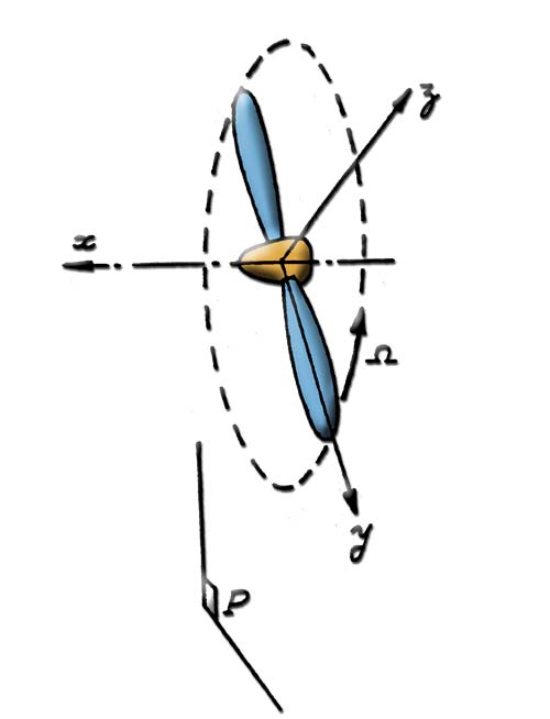
The propeller's references: rotation axis x, blade axis y, plane of rotation P and rotational speed Ω.
- The x axis is the rotation axis, that of the propeller shaft. Far upstream, the fluid arrives parallel to this axis, at the fluid speed.
- The y axis is the blade axis. On a variable pitch propeller, it is the axis the blade pivots about.
- P is the plane of rotation, perpendicular to the x axis. The blades sweep a disc in it: the swept disc.
- Ω is the angular velocity, in radians per second (rad/s) or revolutions per minute (rpm); 1 rpm equals 2π/60, about 0.105 rad/s.
2: The blade divided into elements
The blade is described by a series of sections, placed at different radii along the blade axis. Two neighbouring sections frame a blade element: a small piece of wing, which the blade element method (BEM, Blade Element Momentum) computes as a rotating wing.
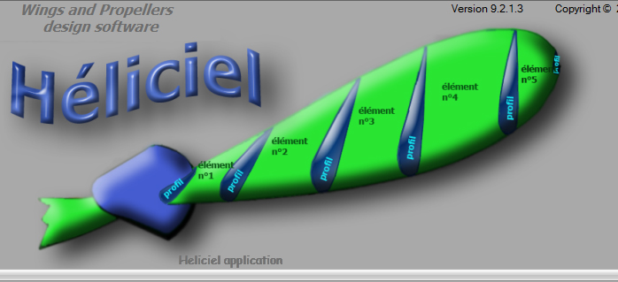
A blade divided into elements, each framed by two sections.
Each section is located by its radius, its distance from the rotation axis. The blade runs from the blade root radius, at the edge of the hub, to the blade tip radius, which is half the propeller diameter.
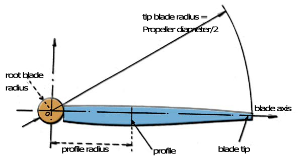
Blade root radius, section radius and blade tip radius (diameter / 2).
3: The blade section and its chord
For the propeller to be efficient, blade sections have an aerodynamic or hydrodynamic shape, like those of a wing. The page on blade sections describes them in detail.
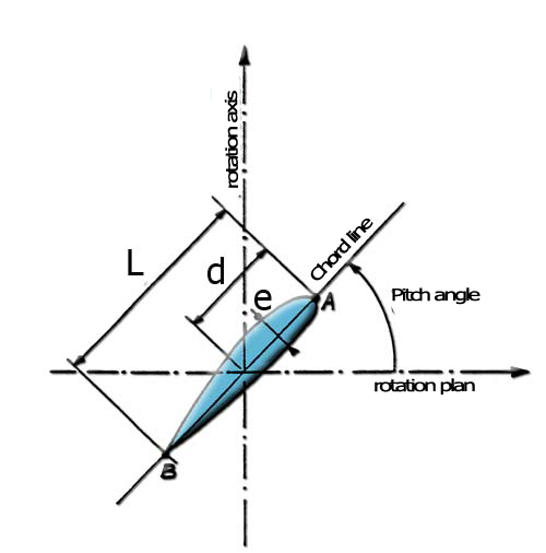
- the chord is the line joining the leading edge to the trailing edge;
- L is the chord length;
- A is the leading edge, B the trailing edge;
- e is the maximum thickness of the section;
- d is the distance between the leading edge and the blade axis.
The angle between the chord and the plane of rotation is the pitch angle of the section. It varies from root to tip: this is blade twist. The pitch angle also sets the geometric pitch of the section, not to be confused with the effective pitch of the propeller: the page on propeller pitch explains both.
4: Apparent velocity, pitch angle and angle of attack
A blade section sees the fluid arrive with two combined velocities: the upstream fluid velocity, along the axis, and the peripheral velocity due to rotation, in the plane of rotation. Their resultant is the apparent velocity; the angle it makes with the plane of rotation is the apparent angle.
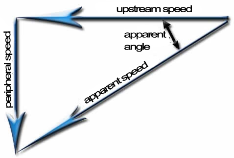
The velocity triangle: upstream fluid velocity and peripheral velocity give the apparent wind.
The angle between the apparent direction of the fluid and the section chord is the angle of attack. On a propulsive propeller, the pitch angle therefore equals the apparent angle plus the angle of attack. The pitch angle of each section is chosen so that the angle of attack is the best one at the operating point.
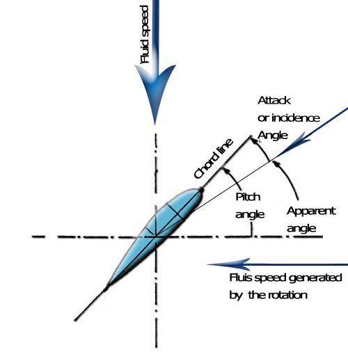
Pitch angle, apparent angle and angle of attack on the same section.
5: The generatrix: skew and rake
The sections line up along the blade following a line, the generatrix. It can be deformed in two ways:
- skew: the generatrix shifts angularly in the direction of rotation, and the blade takes a scimitar shape;
- rake: the generatrix makes an angle with the plane of rotation, and the blade tip is set back behind that plane.
The two effects combine. A skewed generatrix on a twisted blade shifts the sections backwards: it creates induced rake, even when no rake angle is given to the generatrix.
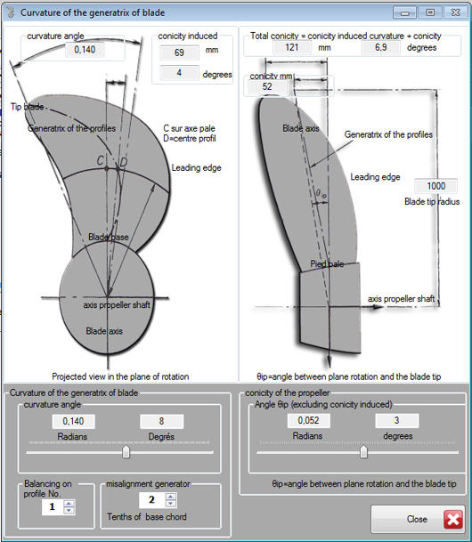
The generatrix settings window in Heliciel: view in the plane of rotation on the left, side view on the right.
The Curvature of the generatrix of blade window sets the curvature angle, the rake angle and the offset of the generatrix. Heliciel computes and displays the rake induced by the curvature, then the total rake of the propeller.
To go further, we can see how the pitch angle varies along the blade with blade twist, or how geometric and effective pitch differ on the propeller pitch page.
 Global site map
 Mecaflux
 Tutorials Mecaflux Pro3D
 Tutorials Heliciel
 Tutorials Heliciel PRO CFD
 Mecaflux Store
 Compare software functions
 Quotes, Orders, Payment Methods
 project technical studies