
The guide vanes set the flow and give the water the rotation the runner needs. Their geometry is set in the Distributor tab.
Kaplan turbine distributor: guide vanes, height b0 and losses
The distributor is the control member of the turbine: its adjustable guide vanes set the flow and give the water its tangential component, which the runner turns into torque. The Distributor tab holds its whole geometry, and the runner diameter too, since the distributor outlet is the runner inlet.
Distributor tab of the left panel. The guide vane opening is set in the control panel. Each block explained here carries a ? help icon in the window: clicking the icon opens the matching section of this page directly.
Contents:
- Runner diameter D: the distributor outlet
- Guide vane axis circle
- b0: distributor guide vane height
- Guide vane profile: number, NACA profile and chord
- Distributor head losses: four Idel'cik terms
Runner diameter D: the distributor outlet
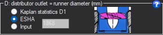
- Choose the diameter source: ESHA, Kaplan statistics D1 or Input.
- Check the diameter in the dimensioned 3D view.
- Run a solver again: the runner is recomputed with this diameter.
In this window, the distributor outlet diameter is the runner diameter. Three sources:
- ESHA: D = 84.5·(0.79 + 1.602·NQe)·√H / N, from the ESHA small hydropower guide;
- Kaplan statistics D1: D1 = 60·U1 / (π·N), with U1 = ξ1·√(2·g·Hn), ξ1 being read on the statistical curve for the current specific speed;
- Input.
D sets the axial velocity in the runner (flow divided by the swept ring) and, with the rpm, the blade tip speed.
Example
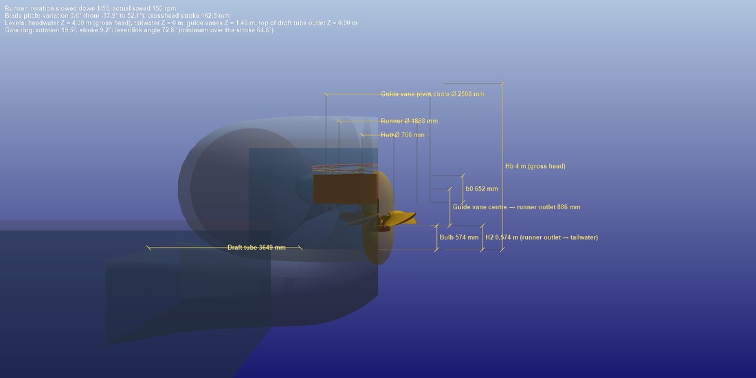
Dimensioned vertical cut in 3D: runner diameter, hub, height b0, axis circle and height H2.
Guide vane axis circle

- Keep the default value (1.2 × D) to start with.
- With an input value, check in the top view that the guide vanes do not touch the runner.
This is the diameter of the circle on which the moving guide vanes pivot, in the optimum opening position. Default: 1.2 × D.
If it is too small, it puts the guide vanes inside the runner or chokes the passage: the throat velocity rises sharply, and the losses with it. Solver 2 can enlarge it by itself when the Euler opening cannot be reached.
Example
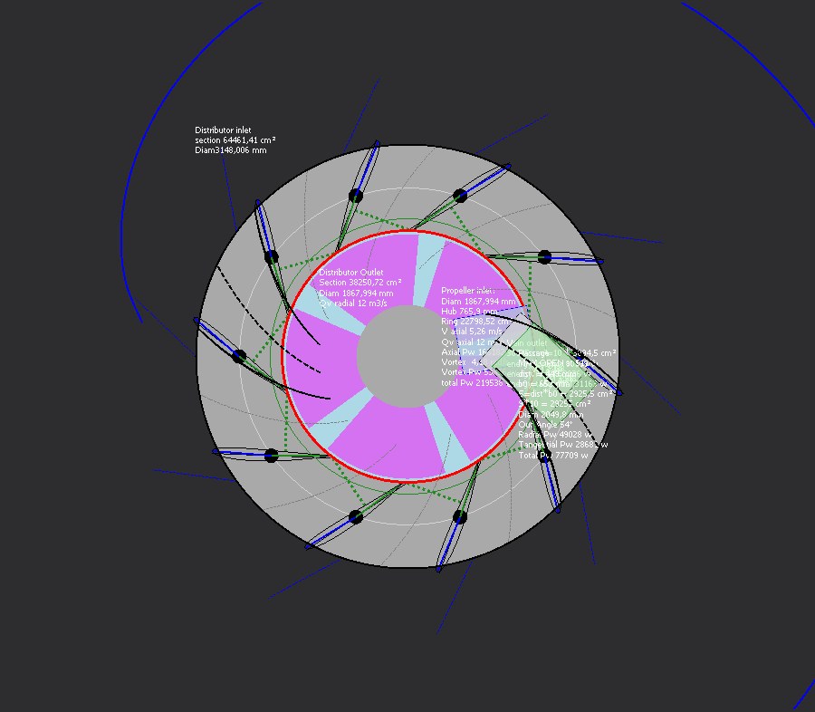
Top view with the guide vane passage and distributor outlet: the axis circle sets where the vanes sit around the runner.
b0: distributor guide vane height
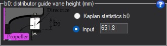
- Choose Kaplan statistics b0 or Input, or equalize the sections from the control panel.
- Check the passage height in the dimensioned 3D cut.
b0 is the height of the passage under the guide vanes. Three sources: Input, Kaplan statistics b0 (ratio b0/D1 read on the similitude curve), or section equalization with the button of the control panel: b0·π·D = π·(D² − d²)/4.
A b0 that is too small accelerates the water in the distributor; too large, it slows it down before accelerating it again in the runner. Both cost head.
Example
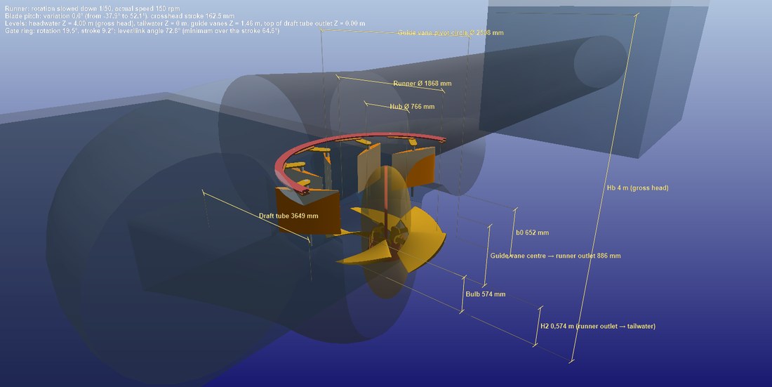
Close-up of the distributor in dimensioned cut: the guide vane height b0 above the runner.
Guide vane profile: number, NACA profile and chord
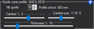
- Set the number of guide vanes.
- Set the thickness, camber and camber position: the NACA name appears in the title.
- Check in the top view that the camber follows the swirl path (dotted lines).
- Number of guide vanes;
- Thickness (% of chord), camber and camber position: three sliders that build a four-digit NACA profile, whose name appears in the block title;
- Profile chord (mm): 1.1 times the side of the polygon formed by the guide vane axes on their circle. It therefore depends on the number of guide vanes and on the axis circle.
In the top view, the dotted lines show the natural path of the swirl: a well-cambered guide vane follows this path instead of striking it.
Example
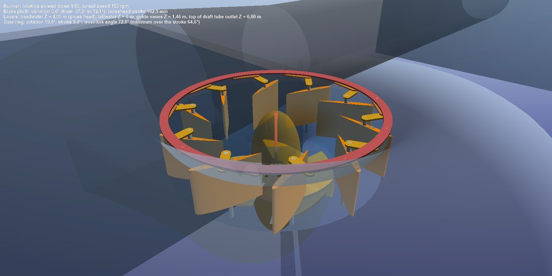
The guide vanes in 3D: NACA profile, number of vanes and chord.
Distributor head losses: four Idel'cik terms
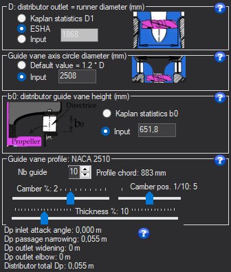
- Read the four losses at the bottom of the tab.
- Spot the largest one and act on the matching setting (orientation, b0, axis circle).
- Compare the total with the other losses in the heads chart.
The distributor is counted as four losses, after Idel'cik, shown at the bottom of the tab:
- inlet angle of attack: difference between the flow direction and that of the guide vanes;
- passage contraction between guide vanes;
- outlet expansion;
- outlet bend: turning from radial flow to axial flow towards the runner;
then their total. This total enters the path losses, plotted in the Results tab. The deviation imposed by the guide vanes creates the swirl the runner recovers: its loss is therefore already counted in the net head Hn.
Example
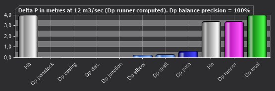
The heads chart: the distributor loss among the path losses.
Going further
The Hydro Turbine design reference page presents the complete method and a worked case. The other help pages of the window:
 Global site map
 Mecaflux
 Tutorials Mecaflux Pro3D
 Tutorials Heliciel
 Tutorials Heliciel PRO CFD
 Mecaflux Store
 Compare software functions
 Quotes, Orders, Payment Methods
 project technical studies