
Foreword introducing function Heliciel software: The software tool has entered the mechanical studies offices. and the engineer or designer seems to have grown in power design, but beware, the "mouse" may force the designer to adopt inappropriate methods, so take care not to "throw the baby out with the bathwater" take the example of using 3D CAD software modules calculations simulating fluid flows by the finite element method. These tools are very powerful and effective open multiple posibilities of controls design. But this type of finite element simulation can only be made that after designing a 3D prototype, it provides information that in retrospect, this amounts to a form of empiricism if one is satisfied with this approach::
- modelize
- simulate the finite element
- search optimization
- modelize
- simulate the finite element .....
- search optimization
- .. .= empiricism...
This type of method is suitable when the shape of the object and the fluid velocity (or object) are predetermined. because the number of trials is relatively reduced, but to design a propeller this method becomes unusable because the induced velocities entries are unknown (the propeller draws air upstream or brakes if a turbine) that the user must be included when calculating, and the optimum twist being a resultant of these speeds, the shape of the model is necessarily an unknown too.
. So designing a propeller in 3D and test with finite element produces very nice designs but is a form of empiricism costly in time and does not necessarily give good results. Prior to model the object, the method of calculating propeller must determine the speed induced by the propeller at the same time as its form, this method exists, its history is summarized on this page, but it presents the mathematical difficulties (convergence of nonlinear equations Resolved by Newton method) as the offices of mechanical studies have left to theorists of fluid mechanics. Heliciel The software has been designed to integrate this method in modern design offices mechanical studies. This does not not exclude the use of 3D CAD model because the optimum blade created using Heliciel in IGS Format may be injected into the CAD!
Propeller calculation methods and their evolution, from Rankine to vortex theory
Propeller calculation methods were built in four stages: the propeller seen as a screw (before 1865), the momentum theory of Rankine and Froude, the blade element theory of Froude and Drzewiecki, then Joukowski's vortex theory. Each stage corrects the limits of the previous one, and modern propeller calculation combines them all. For the full story, see also the history of propeller calculation methods.
As the saying goes, we sit on the shoulders of giants: inventing means observing, but also knowing what our predecessors observed. So let us take a little height, and a little time, to go through this summary. The more general history of the propeller and of propeller calculation is the subject of a separate article.
In this page:
- The propeller seen as a screw (before 1865)
- Rankine, Froude and momentum theory
- Froude, Drzewiecki and blade element theory
- Joukowski and the vortex theory of the propeller
- Comparing propeller calculation methods
- A worked example of each approach
- Why vortex theory corrects blade-tip losses
- What these methods change for the designer
- The propeller calculation methods used in Heliciel
1 : The propeller as a screw: the first calculation method
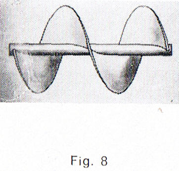
Originally, the propeller was considered a screw, advancing through a fluid just as a screw advances through wood or metal. For the latter, the advance per turn is exactly equal to the pitch of the screw.
People therefore thought the propeller efficiency would reach 100%: the advance per turn would equal the propeller pitch. Without friction, the work needed to turn a screw is exactly the work needed to lift a weight, for example with a jack. Likewise, the work supplied by the engine to turn the propeller would equal the work needed to "pull" the aircraft, still ignoring friction.
But the propeller does not behave that way. The fluid "yields" behind it, so the propeller "slips back" from the position it would occupy if fluids behaved like solids. The useful work per turn is the product of the pulling force and the real advance along the axis in each turn; the efficiency is therefore below 1. We can thus state what is, in a way, the first theory of the propeller.
2 : Momentum theory: Rankine (1865) and Froude (1889)
Rankine went further. In 1865 he established that the action of the propeller is essentially characterised by the acceleration of the mass of fluid passing through it. It follows that the change in momentum per unit time equals the thrust.
Rankine also established that the speed increase the propeller gives the fluid must stay small for good efficiency. In other words, it seemed worthwhile to increase a propeller's diameter indefinitely. This is the "momentum" theory. It gives an ideal efficiency, since it supplies the thrust. However, it does not explain how the thrust passes from the fluid to the propeller, nor, conversely, how engine power passes to the air through the propeller.
Rankine then tried to bring in the friction drag of the blades and the interaction between volumes close to the propeller. It was mainly Froude, in 1889, who enriched the theory. Betz then advanced it by introducing the rotation of the flow linked to the propeller. Even so improved, momentum theory evaluates thrust and efficiency accurately, but says nothing about the corresponding blade shape.
3 : Blade element theory: Froude (1878) and Drzewiecki
As early as 1878, Froude had glimpsed another path: blade element theory, based on knowing the forces the blades exert as they move. A few years later, Drzewiecki developed in his "Théorie générale de l'hélice" the real blade element theory, which Froude had only glimpsed.
The blade "geometry" finally appears. The blade is cut into a large number of elements, perpendicular to the radius. Each element is an airfoil moving at a speed that results from the forward speed and the tangential speed.
This presentation follows the book "L'hélice" by Jean Grampaix (éditions Argenson, Paris, 1966).

Cover of "Théorie générale de l'hélice, hélices aériennes et hélices marines" by S. Drzewiecki (Gauthier-Villars, Paris, 1920).
In the foreword to his "Théorie générale de l'hélice", Drzewiecki sets out blade element theory. Here is the gist of what he says.
- His theory was also extended to air windmills and allowed him to predict new phenomena, which experiment confirmed. He thanks Mr Eiffel and the Auteuil aerodynamic laboratory for the experimental information and tests that helped him complete it.
- Some doubt remained despite his arguments: no direct experiment had established his basic hypothesis. Several scholars, while accepting his ideas for the details, still based propeller theory on the mass of fluid driven back, treated as a cylinder whose base is the disc swept by the propeller.
- For him the two views exclude each other. If the propeller blade acts like a small plank at an angle in a stream, it deflects a limited layer of fluid that moves along with it: there would be as many flows as there are blades, with little or no disturbance between them. In the opposite theory, the flow would be continuous across the whole cylinder section.
- Measurements made until then, upstream and downstream of the propeller, seemed to favour the continuous flow. Drzewiecki explains why: anemometers and the liquid manometers of the Pitot tube have inertia. They cannot follow the rapid speed changes as each blade passes, and show only an average steady state, whereas the real motion is a rapid succession of pulses.
- He therefore built an apparatus free of inertia effects and tested it at the Eiffel laboratory. The experiment succeeded: the flow caused by a propeller blade moves along with that blade, and the fluid between two blades is little disturbed. The cylindrical-flow hypothesis was thus ruled out, and the success of this test encouraged him to publish his study.
4 : Vortex theory of the propeller: Joukowski (1912), Prandtl, Goldstein
After blade element theory came, in 1912, Joukowski's vortex theory of the propulsive propeller. Each blade is treated as a bound vortex, or blade vortex, whose circulation varies along the blade. This variation produces a sheet of free vortices shed from each blade element. It combines the two previous theories, momentum and blade element. It was perfected by the Germans Betz and Helmbold, by von Karman and Bienen, by the English Wood and Glauert, by the Italian Pistolesi, by Lanchester, by Prandtl and by the Japanese Moriya and Kawada.
This theory joins the one we describe for the wing, Prandtl's lifting-line theory.

Cover of "Le développement moderne de la théorie de l'hélice" by Raymond Siestrunck (Gauthier-Villars, 1947).
Raymond Siestrunck's introduction (1947) tells the same story in more detail. This is what we take from it.
- The first methods (since Rankine, 1865) treat the propeller like a turbine. The blade is a series of elements with no interaction between them. The fluid reaches each element with a speed resulting from advance and rotation, and the element deflects the flow. The momentum and angular-momentum theorems then give each element's thrust and torque, and integration along the blade gives the total forces.
- Other methods apply to each element the laws of fluid resistance, determined on elements in uniform translation. Here belong Redtenbacher (1875) and W. Froude (1878); Drzewiecki gives the complete exposition in his Théorie générale de l'hélice (Gauthier-Villars, 1920).
- H.-E. Froude's theory (1889) relates thrust and engine power directly to the propeller's wake. Its analysis of the wake is incomplete: it assumes a uniform slipstream speed over the swept disc, which amounts to a pressure jump across that disc.
- Joukowski (1912) finally links the previous theories. Vortex shedding plays an essential role in energy exchange, and knowledge of the wake had greatly increased since Flamm's experiments (1909). Joukowski lays the foundations of the current theory: the experimental results of lifting surfaces are still applied to each element, but accounting for the interaction of the other elements, whose vortex shedding "induces" additional velocities over the whole blade. The link between induced velocities and the behaviour of one element goes through the circulation, which characterises its lift, by the theorem that now bears the Russian scientist's name. His work dealt only with propellers of constant circulation along the blade, but it precedes the work of the Göttingen school (Prandtl and Betz). When he died in 1921, the propeller problem was entirely posed.
- What followed was harder than for the wing. Vortex theory of the propeller, built on Prandtl's model for the lifting wing, ran into greater difficulties: the additional velocities produced in the wake cannot be evaluated simply for a propeller, and mathematical difficulties slowed the theory. Approximate solutions were nevertheless developed, either to determine the shape of a propeller meeting imposed performance (Goldstein's work, 1929, a rigorous solution of the design problem within the theory's validity range), or for the inverse problem, determining the performance of a given propeller (calculations at least as complicated as those for wings, Glauert, Lotz).
5 : Comparing propeller calculation methods: what each brings, what each ignores
Each stage of this history answers a question the previous one left open. Seeing them side by side explains why modern software relies on none of them alone. We do not repeat the detailed story here, which the page on the history of propeller calculation methods presents; we compare the methods by what they let us predict.
- The propeller-screw gives a theoretical advance per turn, the pitch. It is enough to talk about slip, but it predicts neither thrust nor efficiency, and ignores the fluid altogether.
- Momentum theory predicts the thrust and the best possible efficiency for a given forward speed and disc. It treats the propeller as a black box: it says nothing about chord, pitch angle or airfoil. You cannot design a blade with it alone.
- Blade element theory links the shape of each section to the forces it experiences. It is the first method that lets us design a blade. It assumes, however, that each element sees the undisturbed fluid, as if it were alone in the world.
- Vortex theory corrects that assumption. It calculates the velocity that the wake vortices add to the flow, and the blade-tip losses. It is heavier to put into equations, which long limited its use.
6 : A worked example of each propeller calculation approach
The values below are hypothetical examples, chosen so the calculations can be followed by hand. They are neither measurements nor software results.
Example 1, the propeller-screw. A propeller with a geometric pitch of 0.60 m turns at 5 revolutions per second. If it screwed into a solid, it would advance 0.60 × 5 = 3.0 m/s. The boat actually moves at 2.4 m/s. Its effective pitch is 2.4 / 5 = 0.48 m, and the slip is (0.60 − 0.48) / 0.60 = 20%. The screw does not tell us why the slip is 20% rather than 5%: that needs what follows.
Example 2, momentum theory. A 1 m² propeller disc accelerates air (1.2 kg/m³) from 10 m/s, the forward speed, to 14 m/s in the wake. The speed through the disc is the average, 12 m/s. The thrust is T = ρ A Vd (Ve − V0) = 1.2 × 1 × 12 × 4 = 57.6 N. The ideal efficiency is 2 × 10 / (10 + 14) = 0.83. If we want the same thrust with a less accelerated wake, we need a larger disc: that is Rankine's message.
Example 3, blade element theory. Take the airfoil located 0.50 m from the axis of a propeller turning at 40 revolutions per second (2,400 rpm) and advancing at 30 m/s. Its tangential speed is 2π × 40 × 0.50 ≈ 125.7 m/s. The fluid therefore arrives at √(125.7² + 30²) ≈ 129.2 m/s, at an apparent angle atan(30 / 125.7) ≈ 13.4° to the plane of rotation. With a pitch angle of 18°, the angle of attack is about 4.6°. The airfoil polars then give the Cl and Cd, hence the lift and drag of the element, which we project into thrust and torque. The calculation is then repeated on every element of the blade.
Example 4, vortex theory. It adds to example 3 a velocity induced by the vortices, which changes the apparent angle of each element. The principle is that of the finite-span wing and its lifting line. On the Heliciel-simulated wings shown in that page, an aspect ratio of 4 gives a lift-to-drag ratio of 16 and an aspect ratio of 18 gives 32: wing-tip vortices weigh more the shorter the wing. A long, narrow propeller blade follows the same logic.
7 : Why vortex theory corrects blade-tip losses
On the pressure face of a blade, the pressure is higher than on the suction face. At the blade tip, nothing separates the two faces: the fluid flows around the end to equalise the pressure. The pressure difference, which makes the thrust, therefore vanishes at the tip. The real thrust there is lower than a calculation treating each element in isolation would predict.
Blade element theory alone ignores this flow around the tip. It gives the last element the same lift as if it were in the middle of an infinite blade, and so overestimates the thrust. Vortex theory represents the flow around the tip by vortices that leave the blade tip and travel into the wake. Each one induces on neighbouring elements a velocity that changes their angle of attack, and hence their lift. The calculation then accounts for the thrust drop towards the tip.
This effect depends on the number of blades. With many blades, the fluid has little room to escape between them. With few blades, it leaks more, and the loss grows. Prandtl summarised the effect in a tip-loss correction factor, applied to the thrust and torque of each element; Goldstein, for his part, gave the solution for the optimal circulation distribution on a finite number of blades. We have no universal value to give you: the size of the loss depends on the number of blades, the radius and the operating point.
8 : What these methods change for the propeller designer
For the person designing a propeller, these theories translate into practical questions.
- To size the diameter, momentum theory gives the right order of magnitude: for equal thrust, a large propeller that accelerates the fluid a little is more efficient than a small one that accelerates it a lot.
- To choose chord, pitch angle and airfoil, we need blade element theory, because only it links these choices to the forces.
- To judge the effect of blade count and tip finesse, we need the vortex corrections. A blade that looks good without them may disappoint once the tip losses are counted.
- For a heavily loaded propeller, for example at a drone's static point, simple momentum theory no longer holds; this is the domain of Glauert's correction.
These methods do not contradict one another: they complement each other, and each suits one stage of the design better. A result obtained with any of them remains a model, which must be compared with measurements when the stakes justify it.
9 : Which propeller calculation methods does Heliciel use?
Heliciel calculates the propeller with the blade element method (BEM, Blade Element Momentum), coupled with Froude's momentum theory. It includes the losses according to the vortex theory of the propeller, with Glauert or Goldstein corrections for the load cases where Froude's theory is no longer valid.
To go further, we can detail each stage in the pages on momentum theory, blade element theory for a propulsion propeller, propeller and wing theory, or consult the bibliography on propellers, wind turbines and wings.
 Global site map
 Mecaflux
 Tutorials Mecaflux Pro3D
 Tutorials Heliciel
 Tutorials Heliciel PRO CFD
 Mecaflux Store
 Compare software functions
 Quotes, Orders, Payment Methods
 project technical studies