
Fluid speed relative to the propeller: the speed at infinity upstream
The fluid speed used to calculate the performance of a propeller or a wing is the speed measured upstream, far enough away to be free of any disturbance. Propeller calculation formulas call it the "speed at infinity upstream". For a propeller or wing fitted to a moving vehicle, it is the speed of the vehicle.
In this page:
- Who sets the fluid speed?
- Setting the fluid speed in Heliciel
- The fluid speed is not the speed the profiles see
1: Who sets the fluid speed?
The speed of the fluid or vehicle is generally a given in the specifications of the propeller or wing, and you set it in Heliciel. It takes a different meaning depending on the type of study:
- for a propulsion propeller, the speed is set by the speed of the vehicle;
- for a fan, it is the flow rate of the ventilation duct;
- for a wind turbine, it is the mean wind speed;
- for a tidal turbine or axial turbine, it is the speed of the water current.
For a wing, the speed depends on the power available to overcome drag. We then run speed tests, and the drag and lift forces we obtain tell us whether our wing is correctly sized.
This speed helps determine the operating point of a propeller, together with the rotational speed.
2: Setting the fluid speed in Heliciel
In the Heliciel propeller design software, we change the fluid speed around the propeller or wing in two ways: by dragging the needle of the fluid speed gauge, or by typing directly in the 1: Project specifications tab, 1.3: Operating point sub-tab.
The fluid speed gauge and the entry box of the 1.3: Operating point sub-tab set the same speed: that of the fluid upstream of the blade. Heliciel also shows the speed in kilometres per hour, in knots and, for a duct, the flow rate.
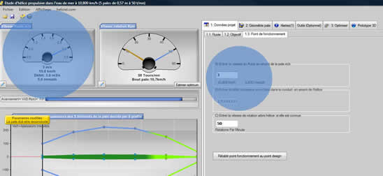
The fluid speed gauge, top left, and the operating point entry box, on the right. In this example, a boat propeller, the speed is 3 m/s, or 10.8 km/h (screenshot of the French interface).
3: The fluid speed is not the speed the profiles see
The speed seen by the profiles of a wind turbine blade, an aircraft propeller or a boat propeller differs from the fluid speed far upstream. The rotation of the propeller or blade creates a tangential velocity. The apparent speed seen by the blade profiles is therefore a combination of the rotational speed and the fluid speed.
Another phenomenon further alters the speed seen by the profile: the induced velocity. Calculating the performance of a wing or propeller largely consists of determining these induced velocities. Calculating them along the blade establishes the angle of attack of the profile, and therefore the performance of the propeller.
To go further, we can see how the rotational speed of the propeller is defined in turn, or how to read the propeller and wing calculation results that follow.
 Global site map
 Mecaflux
 Tutorials Mecaflux Pro3D
 Tutorials Heliciel
 Tutorials Heliciel PRO CFD
 Mecaflux Store
 Compare software functions
 Quotes, Orders, Payment Methods
 project technical studies