
Propeller calculation method used by Heliciel: blade elements (BEM) and Froude theory
The propeller calculation method used by Heliciel is the blade element method, known as BEM (Blade Element Momentum). It cuts the blade into elements along the radius, calculates for each one the velocities the propeller induces in the fluid, then adds up the forces to obtain thrust, torque, power and efficiency. It combines Froude's theory, which deals with the momentum of the fluid, and vortex theory, which deals with the vortices shed by the blades. It is valid only at subsonic speeds.
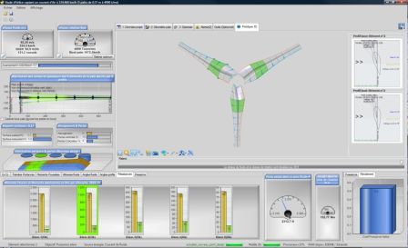
The blade is cut into elements along the radius: each element has its own chord, pitch angle and profile, and is calculated separately.
In this page:
- The blade element method (BEM) to calculate a propeller
- Calculating a ducted propeller with or without blade tip losses
- Induced velocities and forces on a blade element
- Profile database and polars: the data of each element
- Range of validity and deviations from measurements
1 : The blade element method (BEM) to calculate a propeller
The progress of propeller calculation methods, since the beginning of its history, includes different methods that were merged and combined to give the modern blade element method: BEM (Blade Element Momentum).
Let us picture the blade as a stack of small wings, one per element. Each has its profile, chord and pitch angle, and the fluid meets it with a speed and an angle of attack of its own. The blade element method for calculating a propeller combines Froude's theory and vortex theory. It makes it possible to calculate the axial and tangential induced velocities from the performance of the profiles: the drag (Cd) and lift (Cl) coefficients, which depend on the angle of attack and on the Reynolds number.
The method can include the blade tip losses proposed by Prandtl, and various corrections for heavily loaded propellers proposed by Glauert. These methods are detailed on the page on theoretical concepts relevant to the design of propellers and wings.
2 : Calculating a ducted propeller with or without blade tip losses
A duct around a propeller eliminates blade tip losses. It is therefore possible to model a ducted propeller, by estimating the performance with or without blade tip losses. The axial pump below is an example:

An axial pump propeller in the Heliciel 3D view: the green ring represents the duct, which removes blade tip losses from the calculation.
3 : Induced velocities and forces on a blade element
Once the induced velocities are known for each element, the geometry of the blade can be built and the overall performance of the propeller can be evaluated. The following diagram details the induced velocities and forces calculated for a blade element in Heliciel.
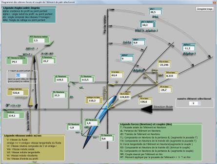
The diagram of a blade element: the fluid speed, the rotation speed and the induced velocities combine into an apparent velocity; the difference between the angle of that velocity and the pitch angle of the element gives the angle of attack. On the left and right, the legend of the angles, velocities and forces (in newtons) of the element.
4 : Profile database and polars: the data of each element
When we want to give a precise shape to our propeller, to control its strength, shaft power, thrust, efficiency or operating point, we must be able to choose and apply profiles along the blade. Gathering the shape definition and the performance data of the profiles of each element, then using them in the calculation method, can prove tedious.
Heliciel automates this step with its interactive database. It selects the best propeller or wing profiles and injects their polars into the calculations: the selection follows one of the profile selection laws.

The interactive profile database: the finesse tab gives, for a profile, the lift coefficient (Cl) and the lift-to-drag ratio versus angle of attack, for each Reynolds number. The buttons on the right apply the profile to a wing, to a blade element or to the duct.
This feature lets Heliciel produce a 3D model optimized in terms of twist, ready to be used in CAD (computer-aided design, 3D files of the blades), while giving the performance in power, torque and thrust. It saves a considerable amount of time when studying a propeller.
Heliciel calculates the induced velocities, the optimum twist and the performance; you impose the profile (or the profile law), the diameter, the speed and the operating point. It thus gives the geometry and performance of an energy-capture or propulsion propeller, and also calculates wings while taking tip losses into account.
5 : Range of validity and deviations from measurements
This method is valid only for subsonic speeds, where the compression of the fluid is negligible. It gives quick results, but a calculation is worth something only if you know what to compare it with. We therefore publish the measured deviations. On four propellers of the Wageningen B series, Heliciel overestimates thrust by 15 to 25% and torque by 17 to 27% compared with the published polynomials, with an efficiency that agrees: see the validation on the Wageningen B series. For aircraft propellers, the validation against wind tunnel measurements (NR640 and DA4002) gives the deviations from the University of Illinois measurements.
To go further, we can see the calculation method for propulsion propellers (boat, aircraft, fan) or for wind turbines, tidal turbines and axial turbines. When the flow is too complex for BEM, the PRO extension of the software calculates it by CFD (Computational Fluid Dynamics): BEM and CFD on the same propeller.
 Global site map
 Mecaflux
 Tutorials Mecaflux Pro3D
 Tutorials Heliciel
 Tutorials Heliciel PRO CFD
 Mecaflux Store
 Compare software functions
 Quotes, Orders, Payment Methods
 project technical studies