
see also: evolution propeller design methods
Static thrust at zero speed computed in CFD A first aircraft propeller designed in Heliciel Propeller at take-off: off-design calculationPropeller at zero speed: static thrust and figure of merit (FOM)
A propeller at zero speed, or "at the fixed point", is a propeller that spins while the boat, aircraft or helicopter does not move forward. It then delivers its static thrust, the thrust of a standing start or of hover. Its propulsive efficiency is zero by construction, so we judge its quality by the figure of merit (FOM), which compares the ideal power with the power the propeller actually absorbs on its shaft.
In this page:
- Why evaluate the static thrust of a propeller
- Calculating a propeller at zero speed in Heliciel
- Efficiency at zero speed: why propulsive efficiency collapses
- The figure of merit (FOM) of a propeller
- Ct and Cp coefficients: propeller or rotor
- Plotting the figure of merit against rotation speed
1: Why evaluate the static thrust of a propeller
The tutorials showed us how to build a propulsion propeller optimized for a given operating point, that is for a given rotation speed and a given fluid speed. See the aircraft propeller design tutorial and the boat propeller design tutorial.
We still need to know what this propeller is worth when the forward speed is zero. This is the case when a boat or an aircraft starts, during a static test, or for a helicopter in hover. The pull the propeller then delivers is called static thrust, and sailors speak of bollard pull.
The stake is practical: a propeller tailored for cruise can perform poorly at take-off. We check it before building, not after.
2: Calculating a propeller at zero speed in Heliciel
The method depends on what we want to know. In both cases, Heliciel computes thrust and torque with the BEM (Blade Element Momentum) method at the speed you impose.
Case 1: a propeller optimized for a cruising speed. We want its performance from a standing start without changing its shape. Two steps:
- We first set the cruise operating point, then update the geometry by clicking Rebuild
 . Heliciel then builds the blade twist optimized for the rotation speed and fluid speed you entered.
 - Next, you enter a nearly zero travel speed, for example 0.01 m/s. A strictly zero fluid speed is not allowed in the calculations: a value close to zero simulates standstill.
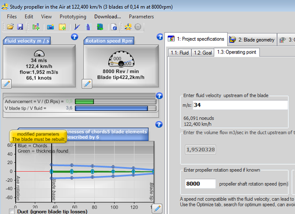
The operating point is set by two values, fluid velocity and rotation speed (here 34 m/s and 8,000 rpm). The Rebuild button then builds the blade twist for this point.
Case 2: the same blade, without rebuilding the twist. To get the performance of the propeller with its current shape, we use the "off design" calculation  . Performance is then calculated without touching the twist. Heliciel flags this mode with "HD" in front of the results, to remind you that the twist is not optimal for the current operating point; thrust and torque are updated.
You can vary the rotation speed and run the "off design" calculation again until you obtain the desired thrust. It is the most direct way to find which rotation speed a given static thrust requires.
Case 3: a propeller that works only at zero speed (or nearly), such as a helicopter rotor in hover. We then update the twist at the nearly-zero-speed operating point: the blade is tailored for standstill, not for cruise.
The Rebuild button builds the blade and its twist for the current operating point; the Off design calculation evaluates performance at the current operating point without rebuilding the geometry. Both are described on the page about the operating point of a propeller.
3: Efficiency at zero speed: why propulsive efficiency collapses
The propulsive efficiency compares the useful power, thrust multiplied by forward speed, with the power delivered to the shaft. At zero forward speed, the useful power is zero: the propulsive efficiency is zero too, whatever thrust is produced.
The notion therefore becomes unusable at the fixed point. Yet the propeller pushes hard, and we want to know whether it does so gracefully or by burning power for nothing. That is exactly the question the figure of merit answers.
4: The figure of merit (FOM) of a propeller
The figure of merit (FM in French, FOM in English) characterizes a propeller at the fixed point, stationary, with zero upstream speed. It compares the minimum power theoretically needed to produce a thrust T, that of an ideal actuator disc (no profile losses, no wake rotation), with the shaft power actually absorbed.
It is at most 1: the closer it gets to 1, the more efficiently the propeller turns shaft power into static thrust. With A the area of the disc swept by the propeller, it is written:
FOM = T3/2 / ( Pshaft × √(2ρA) ) with A = π D² / 4
In this expression, T is the thrust (N), Pshaft the shaft power (W), ρ the fluid density (kg/m³) and D the propeller diameter (m). This form is equivalent to the one using the Ct and Cp coefficients detailed below.
Here we adopt the "propeller" (prop) definition of the coefficients:
- FOM = √(2/π) × Ct3/2 / Cp
- with the thrust coefficient Ct = thrust (N) / ( density (kg/m³) × revolutions per second2 × diameter (m)4 )
- and the power coefficient Cp = shaft power (W) / ( density (kg/m³) × revolutions per second3 × diameter (m)5 ).
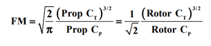
The figure of merit can be written with "propeller" coefficients or with "rotor" coefficients: the result is the same if each formula receives its own coefficients.
5: Ct and Cp coefficients: propeller or rotor
The report NASA/CR-2017-219486 details the possible confusions between propellers and rotors. It warns about the two definitions of the Ct and Cp coefficients, inherited from history and from the habits of each trade: propeller designers and helicopter (rotor) designers do not write them the same way.
We therefore distinguish Cpprop and Ctprop on one side, Cprotor and Ctrotor on the other. Here are their formulations and how to convert one into the other:
• Definition of the thrust coefficient Ct: 
• Definition of the power coefficient Cp: 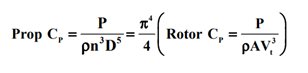
• Definition of the figure of merit: see the formula in the previous section.
The images above give the conversion relations: Ctprop = (π3/4) × Ctrotor and Cpprop = (π4/4) × Cprotor. The figure of merit is the same for a propeller and for a rotor, but only if you use the right formula with the right coefficients. Mixing the two conventions distorts the result by a factor that is anything but trivial.
The literature therefore sometimes gives different definitions of the figure of merit. Heliciel adopts the Ct and Cp coefficients of the "propeller" definition.
6: Plotting the figure of merit against rotation speed
You can run a performance curve test by varying the rotation speed with the multi-point analysis (Optimize tab, multi-point analysis). If you tick "propulsive efficiency", Heliciel plots the propulsive efficiency curve when the fluid speed is above 1 m/s. When it is below 1 m/s, Heliciel takes the figure of merit to plot the curve.
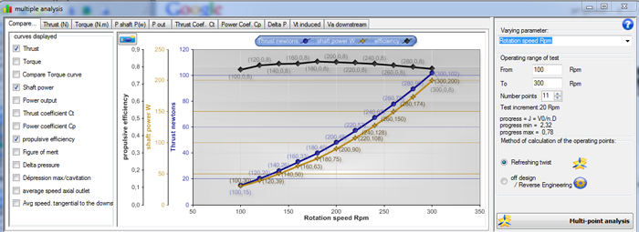
The multi-point analysis plots thrust (blue), shaft power (orange) and propulsive efficiency (black) against rotation speed, here from 100 to 300 rpm at a non-zero forward speed. At a speed below 1 m/s, the black curve is the figure of merit instead of the efficiency.
The reading is valuable: thrust and power vary a lot with rotation speed, so a curve of the figure of merit tells us what the propeller is worth, whatever the effort asked of it.
Static thrust can also be seen in simulation: the practical case drone propeller CFD shows the suction and the jet of a drone propeller in hover, computed in six minutes.
To go further, we can see how the twist and pitch angle of a blade are calculated element by element, how a variable-pitch propeller helps at start-up, or which number of blades to choose for a propulsion propeller.
 Global site map
 Mecaflux
 Tutorials Mecaflux Pro3D
 Tutorials Heliciel
 Tutorials Heliciel PRO CFD
 Mecaflux Store
 Compare software functions
 Quotes, Orders, Payment Methods
 project technical studies