
Design: propeller, turbine, screw, aerial, marine, turbine, tidal, wind, kaplan, foil, wings, 3D. Discover heliciel software:
Contra-rotating propeller: principle, advantages and design example
A contra-rotating propeller is a pair of coaxial propellers turning in opposite directions: the second recovers the rotation the first has given the fluid, and their reaction torques cancel. This article gives a design example for a pair of contra-rotating propellers (contra prop) with the Heliciel propeller and wing design software. We start from a three-blade aircraft propeller of 1,800 mm diameter and design the downstream propeller from the results of the upstream one.
On this page:
- Advantages and drawbacks of the contra-rotating propeller
- Where are contra-rotating propellers used?
- Designing a contra-rotating propeller in Heliciel
- Example: the upstream propeller, a normal propeller
- Example: the downstream propeller, axial speed and tangential flow
- Adding up thrust, torque and efficiency of both propellers
1: Advantages and drawbacks of the contra-rotating propeller
The contra-rotating propeller has several advantages:
- removal of the torque reversal and the gyroscopic torque, hence better manoeuvrability (for aircraft and helicopters);
- straightened wake: the energy lost in making the fluid flow rotate is recovered by the second propeller;
- smaller diameters, for a given thrust.
It also has a drawback: greater complexity, since the engine motion must be transmitted to two shafts turning in opposite directions.

Principle of a contra-rotating propeller: a spherical planetary gear train links the motor shaft to the two propellers and makes them turn in opposite directions.
2: Where are contra-rotating propellers used?
These advantages explain why the contra-rotating propeller is used for marine propellers:

A boat drive unit with contra-rotating propellers: both propellers are carried on the same axis.
as well as for aircraft propulsion propellers:
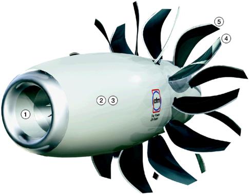
An unducted contra-rotating propeller project for aircraft propulsion: two rows of blades on the same axis.
Some wind turbines are also starting to use the gain from recovering the rotation given to the fluid by the first propeller:

A counter-rotating wind turbine in cutaway view: two rotors on the same axis, the transmission and the generator in the nacelle.
Finally, hydraulic turbines fitted with a stator (guide vanes) can also be regarded as contra-rotating propellers whose first propeller is fixed.
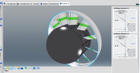
The stator placed upstream of a turbine plays the role of a first, motionless propeller (Heliciel screenshot).
3: Designing a contra-rotating propeller in Heliciel
To be complete, Heliciel had to cover the design of contra-rotating propellers. It does so with a parameter that introduces a tangential flow, which we use in the example below. A multirotor interface also lets you model a pair of contra-rotating propellers directly, or a multirotor system such as an FPV drone or a VTOL ("Vertical Take-Off and Landing"), and test the system's performance.
The File > Contra Rotative project menu opens a contra-rotating pair in the multirotor project window. This function is reserved for propulsive propellers, and its availability depends on the workstation's configuration. Step by step: setting up a contra-rotating pair in Heliciel, then the case studies of the microlight contra-rotating propeller and of the coaxial X8 drone.
The "Contra-rotating propellers" video tutorial presents this function:
In the rest of the page, we go through the method by hand, step by step, to understand what the interface calculates.
4: Example: the upstream propeller, a normal propeller
The contra-rotating propeller consists of two propellers turning in opposite directions. The first propeller is optimized like a normal propeller: we therefore use Heliciel to calculate and create a normal propeller.
For example, let's open an aircraft propeller model and set the parameters as follows:
- a three-bladed propeller (tab 3: Optimize);
- a diameter of 1,800 mm (tip radius 900 mm, root at 17% of the radius, about 153 mm) (tab 2.1 Blade dimensions);
- a root chord of 197 mm and a tip chord of 82 mm;
- chord equation parameters: −0.0002894943 × r² + 0.1508884 × r + 180.6908 (r in mm, chord in mm);
- a rotation speed of 1,000 revolutions per minute (tab 1.3 Operating point);
- a forward speed of 201 km/h (56 m/s) (tab 1.3 Operating point).
With these data, the blade tip speed is about 339 km/h, as Heliciel displays for this example. Here is this design in video:
5: Example: the downstream propeller, axial speed and tangential flow
The second propeller, placed downstream, receives a fluid stream that the upstream propeller has diverted (tangential component) and accelerated (axial component). It must therefore have a twist and a pitch angle optimized with fluid speed parameters slightly different from the first one's, and of course a reversed direction of rotation. To create this downstream propeller, we use the results of the upstream propeller to find the fluid speed at the inlet and the tangential component to set.
In the results area of the upstream propeller, at the element around 0.75 times the blade radius (element 4, the most effective area of the propeller), we read the downstream axial speed: 60.2 m/s, which will be the fluid speed of our second propeller, and the downstream tangential speed: 7.7 rad/s, which will be the tangential flow introduction value of the second propeller.

The results of the upstream propeller: the pop-up help gives, for element 4, a downstream tangential flow speed of 5.236 m/s, or 7.7 rad/s. (The pink labels on this image read "up stream", but the values are those downstream of the propeller.)
After saving the upstream propeller, we turn it into the downstream propeller. We first replace the fluid speed of 56 m/s with the value we read, 60.2 m/s, because this is the speed the downstream propeller sees.

The fluid speed of the downstream propeller is set to 60.2 m/s, the axial speed read downstream of the upstream propeller.
The upstream propeller has also made the flow rotate. We therefore use the Parameters menu, Introduce a tangential flow through upstream (radians / second), to enter the value of 7.7 rad/s we read. Note that the value introduced must be negative in our case, because it is opposed to the propeller's direction of rotation (the propeller's direction of rotation is positive).

The menu that introduces the average upstream tangential flow: the value −7.7 rad/s shows in red next to the menu. The pop-up help recalls that this function models the action of another propeller or of guide vanes (turbine stator).
For the downstream propeller, two quantities come from the upstream propeller: the fluid speed (Project data tab, operating point) and the average upstream tangential flow (Parameters menu). Heliciel then calculates the twist and performance of the downstream propeller with these imposed values. The menu tooltip notes that this function is in beta test.
All that remains is to start the rebuild with these new data, to calculate the twist and the performance of the downstream propeller.
Before exporting the geometry to your CAD software in IGES (IGS) format, the direction of rotation must be reversed in the 3D tab, so that the geometry is rebuilt inverted:

In the Prototype 3D tab, the Direction of rotation menu offers "right-hand propeller" and "left-hand propeller": the downstream propeller takes the direction opposite to the upstream one.
6: Adding up thrust, torque and efficiency of both propellers
The performance of the upstream and downstream propellers add up. The thrusts add, and so do the shaft torques and powers, if we want the total thrust, torque and power of the contra-rotating propeller. Since the two propellers turn in opposite directions, their reaction torques oppose each other on the airframe: that is what removes the torque reversal.
The downstream propeller's efficiency can sometimes exceed 1. Heliciel calculates it without accounting for the energy contributed by the tangential flow introduced, which is recovered and therefore gives an abnormal power surplus. The average of the two propellers' efficiencies gives an overall efficiency that is more realistic and below 1. Another way to form it is to divide the total useful power (total thrust × forward speed of 56 m/s) by the total shaft power.
The contra-rotating propeller design function is even easier to use with Heliciel's multirotor interface:
To go further, we can set the distance between propellers and the downstream speed of a microlight propulsor, or compare a contra-rotating propeller with other aircraft propellers.
 Global site map
 Mecaflux
 Tutorials Mecaflux Pro3D
 Tutorials Heliciel
 Tutorials Heliciel PRO CFD
 Mecaflux Store
 Compare software functions
 Quotes, Orders, Payment Methods
 project technical studies