
The contra-rotative project is not a multirotor with two rotors: half the settings disappear, and another one appears — the distance between the two propellers.
Contra-rotative pair: setting up two coaxial propellers in Heliciel
Two coaxial propellers turning in opposite directions: the arrangement cancels the reaction torque, recovers part of the rotational motion left by the upstream stage, and fits in a reduced diameter. Heliciel treats it as a project family of its own — and that matters, because half the multirotor settings no longer make sense here.
- Tutorial outline:
- Checking that the project qualifies
- Opening the contra-rotative project
- What disappears compared with the multirotor
- Setting the distance between propellers
- Upstream stage, downstream stage
- Reading the interaction
1: Checking that the project qualifies
Contra-rotation is reserved for propulsion propellers. On an energy capture project — wind turbine, hydro turbine, turbine — the menu entry refuses and says why: this is not an interface limitation, it is that the interaction model between two stages does not have the same meaning for a machine that extracts energy.
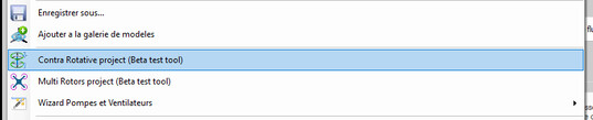
The menu entry
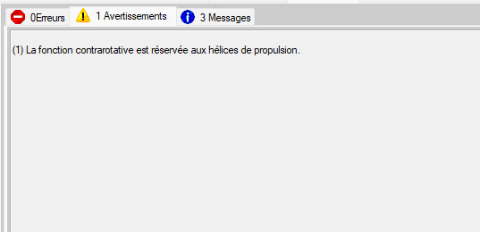
On an energy capture project, the function refuses and gives its reason
2: Opening the contra-rotative project
Files menu > Contra Rotative project. The project is set up with a single arm and two coaxial propellers, and the ContraRotative propeller geometry: group becomes the centre of the work.
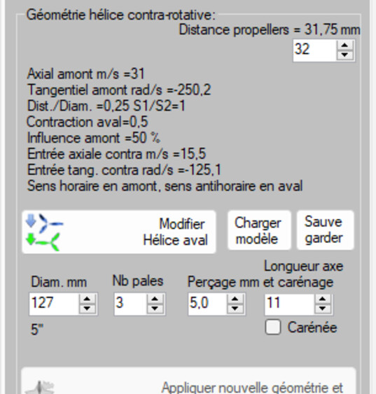
The geometry group specific to the contra-rotative pair
3: What disappears compared with the multirotor
Better said at once, it saves you looking:
- no flight study: the Frame Pitch angle tests group is disabled;
- no structure drag: the base, the arms and the modules are not counted in the drag. Only the ducts, if there are any, drag.
This is not an oversight: a contra-rotative pair is sized on a bench, on its axis; the craft that will carry it is treated as a multirotor project.
4: Setting the distance between propellers
This setting, unavailable in a framed project where it is derived from the geometry, becomes editable here. And it is the interesting parameter: too close, and the downstream stage works in a wake that has had no time to reorganise itself; too far, and you lose the compactness that justified the arrangement in the first place.
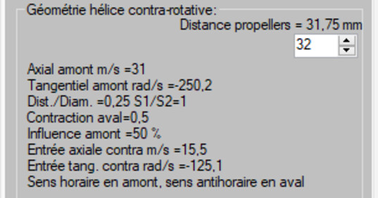
The distance between the two stages, entered directly
5: Upstream stage, downstream stage
Each stage carries its own geometry. The downstream stage receives a flow already accelerated and already set into rotation by the upstream stage: its optimal pitch is not that of the upstream one, and there is no reason for the two stages to be identical.
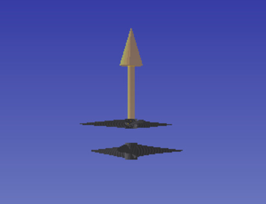
The two stages in 3D
6: Reading the interaction
The result gives the thrust and the torque of each stage. That is where the arrangement is judged: the residual torque of the assembly, the share of rotation recovered by the downstream stage, and the price paid in efficiency compared with a single propeller of the same thrust.
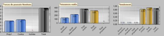
Thrust and torque, stage by stage
Going further: the theory page on the contra-rotating propeller and the multirotor project.
 Global site map
 Mecaflux
 Tutorials Mecaflux Pro3D
 Tutorials Heliciel
 Mecaflux Store
 Compare software functions
 Quotes, Orders, Payment Methods
 project technical studies