
Heliciel breaks the calculated blade down into skin, ribs and spars, and outputs the cutting sheet in DXF.
Kit: the blade as plates to assemble
Not every blade is made by 3D printing or machining. Construction from plates — a framework of ribs and spars, dressed with a skin — remains the most accessible route for a large wind turbine blade, a test blade, a towing tank model. Heliciel breaks the calculated blade down into cuttable parts, and outputs the sheet.
- Tutorial outline:
- Build the prototype, then open the kit
- The skin
- The transverse ribs
- The radial spars and the material
- Interlocking and the DXF sheet
1: Build the prototype, then open the kit
The kit is derived from the 3D geometry: update the build state and rebuild the model before opening the window, otherwise the function will remind you.
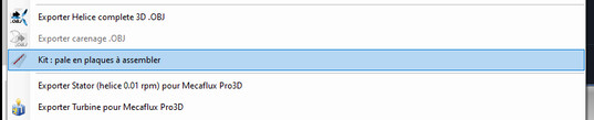
The menu entry
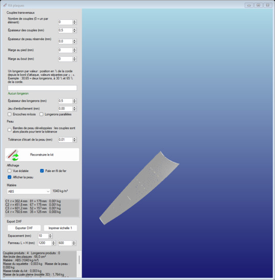
The kit window: the blade broken down into parts
2: The skin
The Skin group sets how the blade is dressed: its thickness — Skin thickness reserved (mm), which has to be filled in for the skin to be displayed at all — and the way it is cut. The Developed skin strips option lays the skin out flat as strips, and the Skin deviation tolerance (mm) decides how far a strip may depart from the true surface before another rib is placed. It is the skin that gives the final aerodynamic shape; the framework only holds it.
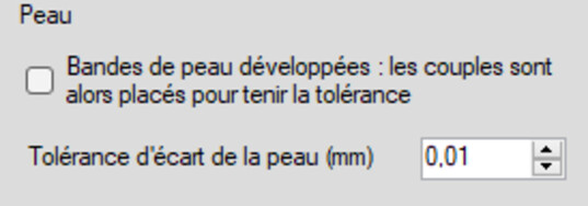
The skin settings
3: The transverse ribs
The Transverse ribs are the cross sections that impose the aerofoil at each radial station. Their number is a compromise: few ribs, and the skin sags between them; many ribs, and the blade is heavy and long to assemble. Number of ribs (0 = one per element) leaves the choice to you or to the discretisation.
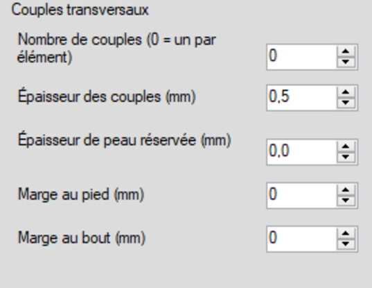
The ribs: the aerofoil, station by station
4: The radial spars and the material
The Radial spars run from root to tip and take the bending; the Material group sets the material of the kit. The Parallel spars option keeps the spars parallel to one another rather than following the twist, and One spar per value: position in % of chord places them where you want them. These two settings are thought out together, and they are checked elsewhere: blade strength has its own page.
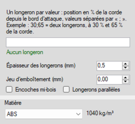
Spars and material
5: Check the interlocking, then output the sheet
The Display group shows the kit exploded or assembled: this is the visual check before cutting, the one that shows a notch falling in the right place. Half-lap notches and Joint clearance (mm) govern how the parts fit into one another. The DXF export group then produces the sheet of parts, ready for laser cutting, for the CNC, or for printing at scale 1 to mark out by hand.
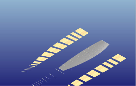
The exploded view: check before cutting
 Global site map
 Mecaflux
 Tutorials Mecaflux Pro3D
 Tutorials Heliciel
 Tutorials Heliciel PRO CFD
 Mecaflux Store
 Compare software functions
 Quotes, Orders, Payment Methods
 project technical studies