
A surf-foil rider wants to draw his own front lifting wing, printed and moulded in carbon. The data:
- Mass to carry: 85 kg (rider + board + foil) → target lift 834 N;
- Target flying speed: 6 m/s (~21 km/h) — the pace at which the foil must carry the whole system;
- fresh water (inland water), wing submerged under a mast of about 80 cm.
As for the RC aircraft wing, there is no optimiser on a wing: you set, you read the lift, you iterate. But in water each square decimetre carries 800 times more than in air — areas become tiny and each degree of angle of attack weighs tens of newtons.
- Organisation and design phases:
- Start from the hydrofoil model
- Too small? Enlarge the wing rather than force the angle of attack
- Bracket the flying point: 4° and 5°
- Lift and drag against speed: the take-off
- Summary and model to download
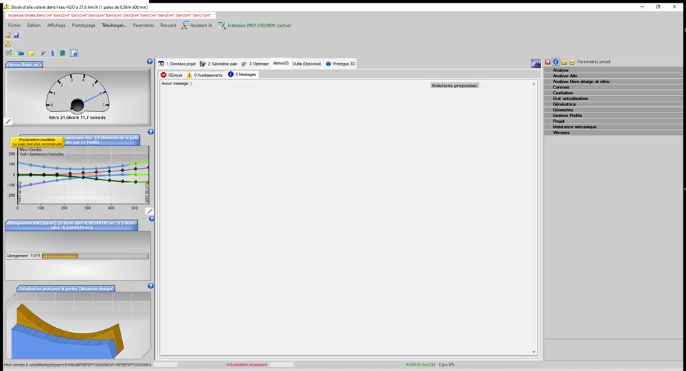
1: Start from the hydrofoil model: Heliciel's “hydrofoil” model is already in fresh water (the fluid is part of the model — careful: if you start from an AIR wing project already open, do change the fluid!). Its chord law is not linear: wide at the root, narrower in the middle, widened again at the tip — that is the model's shape, which we keep.
2: Too small? Enlarge: first trial with a 750 mm span: at 5 m/s the wing only carries 227 N at the angles of attack of maximum lift-to-drag ratio, and even pushed to 8° angle of attack it levels off at 415 N — with a collapsing lift-to-drag ratio. The lesson holds for all foils: when lift is short by more than half, it is not the angle of attack that must be forced, it is the area that must be enlarged. We raise the span to 1,120 mm (Heliciel rescales the planform) and the take-off to 6 m/s.
3: Bracket the flying point: with a uniform angle of attack imposed on the 10 elements of the wing:
| Uniform angle of attack | Lift (N, complete wing) | Drag (N) | Power to overcome (W) |
| 4° | 804 | 32.0 | 192 |
| 5° | 984 | 41.1 | 246 |
Our 834 N target falls between the two lines: the actual flying point lies between 4 and 5° of trim, exactly what the rider adjusts all the time through foot pressure. Let us keep the geometric setting corresponding to 4° as the construction reference. The drag of the wing alone (~35 N in flight) gives the order of magnitude of the pull required — mast and stabiliser add to it: that is why a wing-foil wing calls for ~50-60 N of total pull.
4: Lift against speed — the take-off: at a frozen setting (4°), the multi-point analysis sweeps the speed from 3 to 9 m/s. Values for the half-wing (the complete wing carries twice as much):
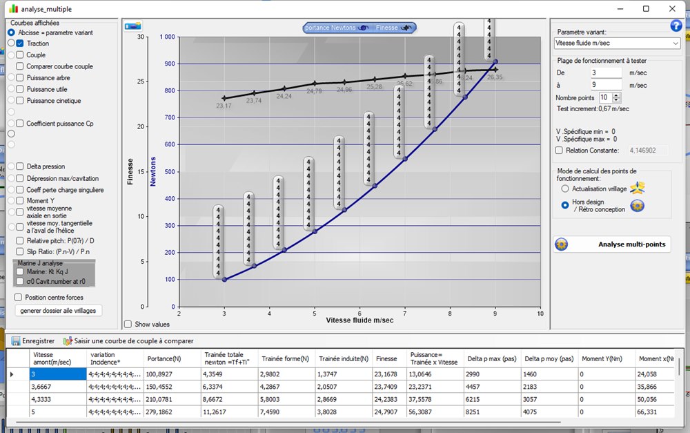
| Speed (m/s) | Lift ½ wing (N) | Complete wing (N) | L/D |
| 3 | 101 | 202 | 23.2 |
| 4.3 | 210 | 420 | 24.2 |
| 5 | 279 | 558 | 24.8 |
| 6 (interp. 5.7-6.3) | ~400 | ~800 | 25.1 |
| 7 | 548 | 1095 | 25.6 |
| 9 | 907 | 1814 | 26.3 |
Reading: lift grows as the square of the speed: the foil “takes off” around 6 m/s at 4° of trim (the complete wing reaches the ~830 N), earlier if the rider pitches up to 5°. At 7 m/s one would have to fly at a lower angle of attack (the wing would carry 1,100 N at 4°: the rider reduces the trim, the lift-to-drag ratio stays excellent). The maximum depression on the upper surface stays moderate (26.6 kPa at 9 m/s): no cavitation risk at these speeds — the real danger of the foil is ventilation (air sucked down from the surface), a matter of mast design and flying depth.
5: Summary and model to download
- Surf-foil front wing: span 1,120 mm, chords 239/134 mm (model law), aspect ratio 9.9, fresh water;
- flight: 834 N carried between 4 and 5° of trim at 6 m/s; wing drag ~35 N; L/D ~25;
- take-off around 6 m/s (4°), earlier when pitching up;
- central lesson: in water, the area is computed to the square decimetre — enlarging the wing is always better than forcing the angle of attack.
The complete project can be downloaded here: hydrofoil_surf_1120mm.hlc (open it with Heliciel). It is also included in the models supplied with the software. The STL/STEP export will give you the mould or the machining master.
I remain at your disposal for any remarks or further information at contact@heliciel.com
- JF Iglesias, Heliciel developer.
To see the pressure around the section and read the lift on the whole foil, read the case study hydrofoil CFD: the same approach as for a wing, with cavitation to watch.
 Global site map
 Mecaflux
 Tutorials Mecaflux Pro3D
 Tutorials Heliciel
 Tutorials Heliciel PRO CFD
 Mecaflux Store
 Compare software functions
 Quotes, Orders, Payment Methods
 project technical studies