
An aeromodeller is designing a high-wing RC trainer and wants to check that its wing will carry the aircraft in cruise with a comfortable stall margin. The data:
- Total mass in flight: 1.8 kg → required lift 1.8 × 9.81 = 17.7 N;
- Cruise: 15 m/s (54 km/h);
- Span: 1.4 m (Heliciel works on the 700 mm half-wing and displays the results of the complete wing), chord 220 mm at the root, 140 mm at the tip;
- section of the supplied model's law: NACA 2411 on the root side (maximum lift-to-drag ratio 71 at the Reynolds number of 200,000 met in flight).
A particularity of wings in Heliciel: there is no objective to optimise. A propeller has an rpm the software can search for; a wing has no free variable — you set the geometry and the angle of attack, read the lift, and iterate. That is exactly the approach of this tutorial.
- Organisation and design phases:
- Load the wing and set the geometry
- Iterate the angle of attack towards the target lift
- The wing polar: lift-to-drag ratio and stall
- Summary and model to download
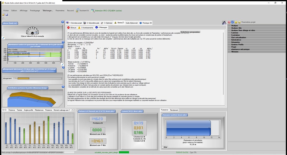
1: Load the wing and set the geometry: the “wing” model is loaded then brought to our dimensions (half-wing 700 mm, chords 220/140 mm). First computation at 15 m/s, each section left at its angle of attack of maximum lift-to-drag ratio:
- lift (complete wing): 14.6 N — not enough for our 17.7 N;
- total drag 0.79 N, aspect ratio 7.7;
- Heliciel reports “irregular angles of attack” (from 0 to 6° depending on the element): since the polars are tabulated, the maximum lift-to-drag ratio of each segment falls at different angles — a “staircase” wing, unrealistic to build.
2: Iterate the angle of attack: we impose a UNIFORM angle of attack over the whole wing (flat wing, no twist — the choice of construction simplicity) and iterate:
| Uniform angle of attack | Lift (N) | Drag (N) | L/D |
| 4° | 16.38 | 0.93 | 17.6 |
| 5° | 18.54 | 1.12 | 16.6 |
At 5° angle of attack, the 18.5 N of lift covers our 17.7 N with a 5 % margin: adopted. The power to overcome in cruise is only 16.8 W (drag 1.12 N × 15 m/s): that is the wing's share — fuselage and tail surfaces will add to it.
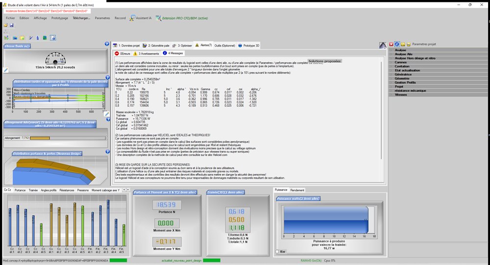
An instructive detail: by selecting a wing element in the 3D area, Heliciel displays its two sections with the downwash — the finite-span wing deflects the air downwards, so that at 5° of setting the central element only “sees” 3.6° effective. That is induced drag in a picture, and the reason why a 2D section computation is never enough to predict a wing.
3: The wing polar: the multi-point analysis sweeps the angle of attack (on a wing project, the “rpm” sweep axis becomes the angle of attack). Values for the half-wing, as returned by the analysis table:
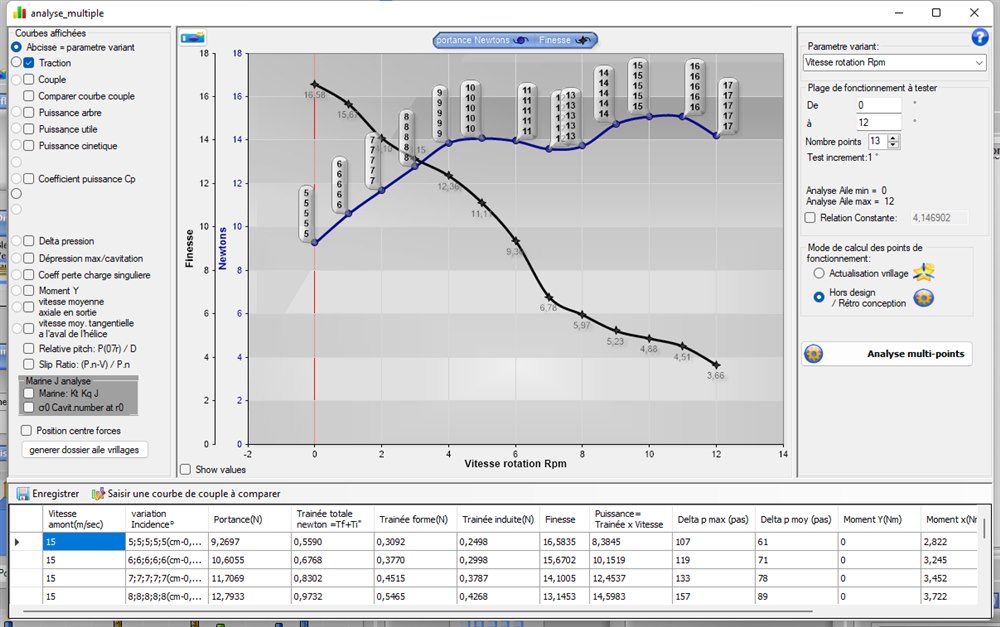
| Angle of attack | Lift ½ wing (N) | Drag ½ wing (N) | L/D |
| 5° | 9.27 | 0.56 | 16.6 |
| 7° | 11.71 | 0.83 | 14.1 |
| 9° | 13.88 | 1.12 | 12.4 |
| 10° | 14.09 | 1.27 | 11.1 |
| 11° | 13.96 | 1.49 | 9.4 |
| 12° | 13.60 | 2.00 | 6.8 |
| 15° | 15.10 | 3.09 | 4.9 |
Reading: lift levels off around 10° — the stall begins (lift stagnates then falls while drag soars; the apparent rise towards 15° goes with a lift-to-drag ratio collapsed to 4.9: the wing “ploughs”). Our cruise flight at 5° therefore keeps 5° of reserve before the stall. The maximum useful lift (~28 N for the complete wing at 10°) also gives the minimum flying speed: v ≈ 15 × √(17.7/28.2) ≈ 11.9 m/s — below that, the aircraft no longer flies (the author's computation from the table values).
4: Summary and model to download
- Wing 1.4 m × (220/140 mm), NACA 2411 section, uniform angle of attack 5°, aspect ratio 7.7;
- cruise at 15 m/s: lift 18.5 N (5 % margin on the 17.7 N required), drag 1.12 N, L/D 16.6, 16.8 W to overcome;
- stall around 10° angle of attack; minimum speed ≈ 12 m/s;
- the wing approach: set → read → iterate (no optimiser), and watch the downwash.
The complete project can be downloaded here: aile_rc_1400mm_15ms.hlc (open it with Heliciel). It is also included in the models supplied with the software. To go further: the advanced wings and foils tutorial.
I remain at your disposal for any remarks or further information at contact@heliciel.com
- JF Iglesias, Heliciel developer.
To watch the air speed up over the upper surface and read lift and drag on the whole wing, read the case study wing CFD: a wing simulated at three mesh refinements.
 Global site map
 Mecaflux
 Tutorials Mecaflux Pro3D
 Tutorials Heliciel
 Tutorials Heliciel PRO CFD
 Mecaflux Store
 Compare software functions
 Quotes, Orders, Payment Methods
 project technical studies