
Tutorial: designing the rotor of a 3-metre home wind turbine with Heliciel
A private individual wants to fit a small horizontal-axis wind turbine to a country house. The specification, drawn up from data collected on site:
- Reference wind speed: 6 m/s (usable average recorded by an anemometer installed for one year on a 12-metre mast, open ground);
- Site altitude: 200 metres (it sets the air density, hence the available power);
- Rotor diameter limited to 3 metres by the permit and the size of the mast;
- A direct-drive permanent-magnet generator (no gearbox), whose rated speed lies between 200 and 300 rpm;
- 3 blades, to limit vibration and manufacturing cost.
Aim of the tutorial: obtain the blade with the optimum twist for this site, know the power and torque that can really be recovered, and check that the optimum rotation speed does fall within the generator's range. The final project is provided at the bottom of the page in .hlc format.
Written by JF Iglesias (Heliciel developer).
- Organisation and design phases:
- Start from the wind turbine model supplied with Heliciel
- Set the fluid of the site (air, 15 °C, altitude 200 m)
- First design point at 6 m/s
- Search for the optimum rotation speed
- Explore the blade sections… and understand why the “best local section” is not enough
- Plot the power curve against wind speed
- Summary, noise, and model to download
1: Start from the wind turbine model: in Heliciel, File menu > open a “wind turbine” model. The supplied model is a 4-metre, 3-blade rotor set at 180 rpm: a sound starting point, which we are going to adapt to our site. The “3D prototype” tab shows the machine as loaded:
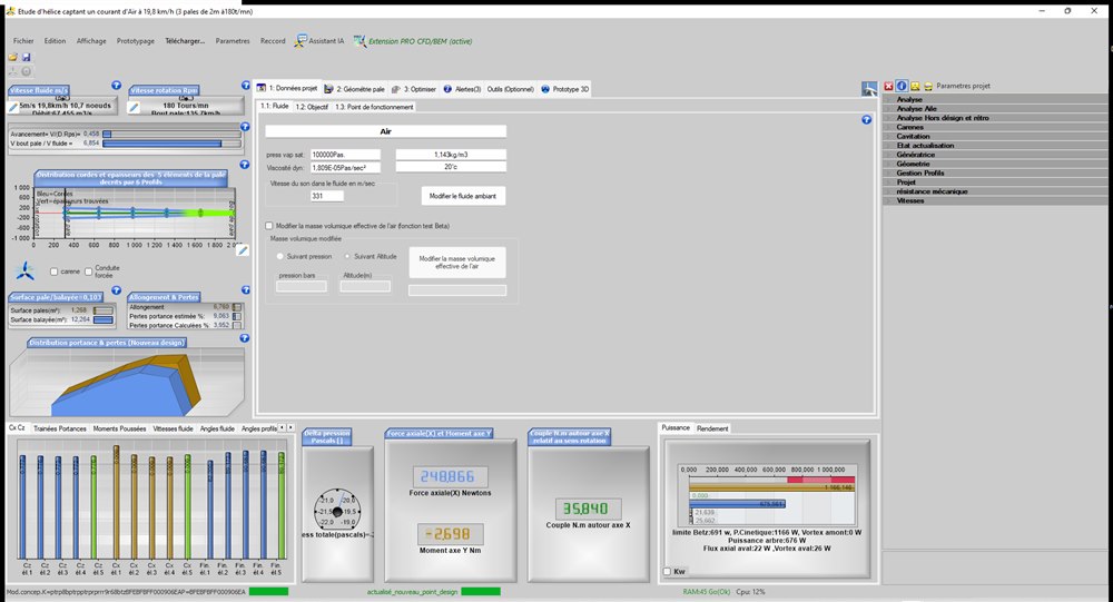
In the “2: Blade geometry > blade dimensions” tab, we bring the diameter down to 3,000 mm. Heliciel automatically scales the chords: 300 mm at the blade root, 75 mm at the tip.
2: Set the fluid of the site: “1: Project data > select ambient fluid” tab, we choose air at 15 °C and enter the site altitude: 200 metres. Heliciel then computes:
- air density: 1.2049 kg/m³;
- atmospheric pressure at the site: 99,600 Pa.
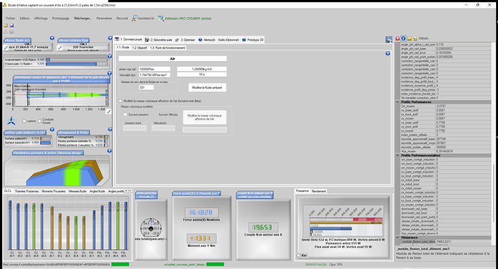
This setting matters: wind power is proportional to density. A wind turbine computed “at sea level” (1.225 kg/m³) would overestimate the output of a site at altitude. Note, at the bottom right of the screen, the permanent results banner: axial force, torque about the X axis, and the power graph that places the shaft power against the Betz limit and the kinetic power crossing the rotor.
3: First design point at 6 m/s: in “1.3: operating point”, we enter a fluid speed of 6 m/s and keep for now the rpm inherited from the model (180 rpm), then we rebuild the optimum twist. Heliciel computes the design point:
- shaft power: 382 W;
- power coefficient Cp = 0.426 (reminder: the Betz limit is 0.593);
- torque: 20.3 N·m — positive: the machine produces energy;
- tip speed ratio (blade tip speed / wind speed) λ = 4.71.
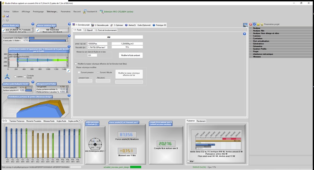
A Cp of 0.426 is fair, but energy is being left on the table: nothing says that 180 rpm is the optimum speed for OUR wind and OUR diameter. That is exactly the optimiser's job.
4: Search for the optimum rotation speed: “3: Optimise > automatic search for optimum efficiency” tab. Heliciel sweeps the rotation speeds, rebuilding the optimum twist at each trial, and keeps:
- optimum rpm: 250 rpm (instead of 180);
- Cp = 0.573, i.e. 96.6 % of the Betz limit;
- shaft power: 514.5 W (+35 % compared with the first trial!);
- torque: 19.65 N·m; tip speed ratio λ = 6.54;
- axial thrust on the mast: 162 N — to be kept for sizing the mast and its anchoring.
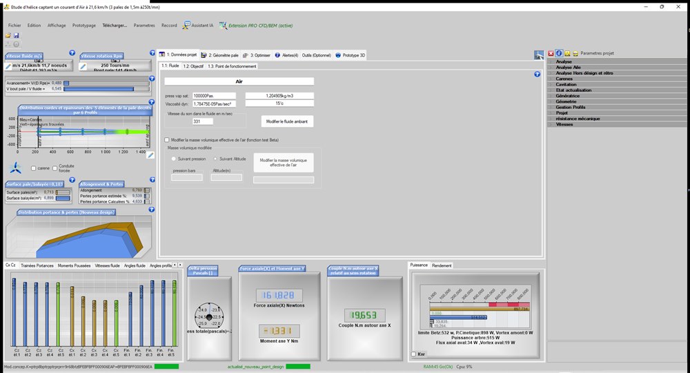
Good news: 250 rpm falls right in the range of our direct-drive generator (200-300 rpm), with a torque of about 20 N·m. The λ of 6.5 is typical of a fast three-blade rotor — consistent with what theory teaches (optimum λ ≈ 7 for 3 blades).
5: Explore the sections… and understand: the wind turbine model uses the NACA 64A410 section (maximum lift-to-drag ratio 89 at the Reynolds number of 300,000 met around 0.75 R). Can we do better? We asked Heliciel to apply, blade element by blade element, the section of best lift-to-drag ratio in the database at the actual Reynolds number of each element. An unexpected and very instructive result:
- the database proposes 5 different sections along the blade (B7_85, NACA 6412, B5_60…);
- but the overall Cp DROPS to 0.501, and Heliciel reports “irregular angles of attack” along the blade (jumps of 3° to 6° between neighbouring elements);
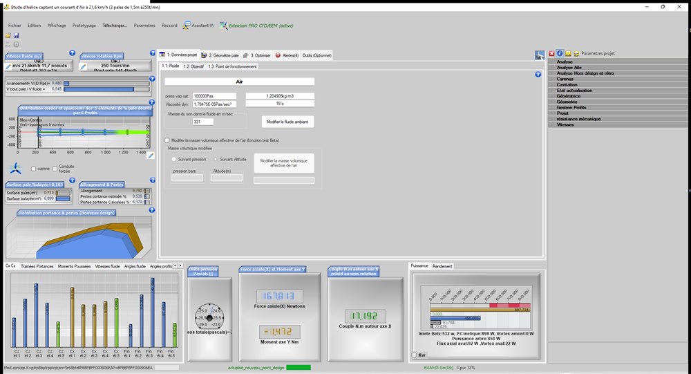
The lesson: the best section of each element taken in isolation does not give the best rotor. The elements interact through the induced velocities, and a saw-tooth distribution of angles of attack degrades the whole. We also tried the NACA 6412 (highly cambered, lift-to-drag ratio 149!) over the whole blade: the optimum then falls back to 200 rpm with Cp = 0.567 and a higher torque (24.3 N·m) — interesting for a slower generator, but Heliciel reports a loading at the limit of downstream flow reversal. We therefore return to the original NACA 64A410 at 250 rpm: Cp 0.573, no error. The section of the supplied model was already the right choice for this tip speed ratio — no coincidence, it is the one chosen in the historical wind turbine tutorial.
6: The power curve against wind speed: our wind turbine will not only see 6 m/s. In the multi-point analysis (“Tools (Optional) > multiple analysis” tab), we sweep the wind speed from 3 to 12 m/s in “Off-design” mode (the blade geometry stays frozen — it is our actual blade!) and at constant tip speed ratio λ = 6.545: this is the behaviour of an MPPT controller that keeps the rotor at its best efficiency by adjusting the rpm in proportion to the wind.
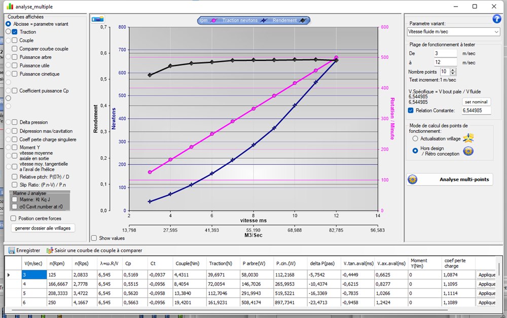
The black curve (efficiency Cp) stays remarkably flat: between 0.52 and 0.576 over the whole range — this is the whole point of constant-λ control. By simply changing the displayed curves (no recomputation), one reads the shaft power and the kinetic power of the wind:
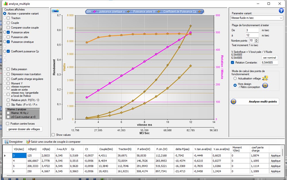
The values of the analysis table (taken as they are from the software):
| Wind (m/s) | Rpm | Cp | Torque (N·m) | Shaft P (W) |
| 3 | 125 | 0.517 | 4.4 | 58 |
| 4 | 167 | 0.552 | 8.4 | 147 |
| 5 | 208 | 0.562 | 13.4 | 292 |
| 6 | 250 | 0.566 | 19.4 | 508 |
| 7 | 292 | 0.573 | 26.8 | 817 |
| 8 | 333 | 0.574 | 35.0 | 1221 |
| 9 | 375 | 0.574 | 44.3 | 1740 |
| 10 | 417 | 0.575 | 54.8 | 2390 |
| 11 | 458 | 0.576 | 66.4 | 3187 |
| 12 | 500 | 0.573 | 78.6 | 4117 |
Practical reading: at 6 m/s we recover about 508 W at the shaft; in a strong wind (12 m/s) the machine would climb to 4.1 kW and 500 rpm — the regulation (furling, stall or braking) will have to cap it well before that, otherwise generator and blades would be in danger. This table also gives the torque at each rpm: the complete characteristic to hand to the generator winder.
7: Summary and model to download
- Three-blade rotor Ø 3 m, NACA 64A410 section, optimum twist computed at 6 m/s / 250 rpm;
- Cp = 0.573 (96.6 % of Betz), shaft power 514 W at the design point;
- torque 19.65 N·m at 250 rpm: compatible with a direct-drive permanent-magnet generator;
- blade tip speed 39.3 m/s (141 km/h) and blade passing frequency 12.5 Hz (harmonics 25 and 37.5 Hz): slow blade tip = quiet wind turbine — a neighbourhood criterion not to be neglected;
- axial thrust 162 N at the design point (to be passed on to the mast computation).
The 3D model of the final rotor, rendered by Heliciel (in the software it can be handled with the mouse; the blue X arrow shows the flow direction):
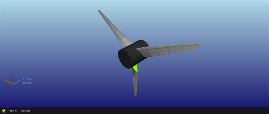
The complete project can be downloaded here: eolienne_domestique_3m.hlc (open it with Heliciel). It is also included in the models supplied with the software. From this project you can export the blade as STL/STEP/IGES for 3D printing or machining, draw the manufacturing drawings, or carry the study further (number of blades, mechanical strength…).
The computed performance is theoretical (smooth surfaces, XFoil polars): allow the usual margins and run cautious trials — see the software's warnings.
I remain at your disposal for any remarks or further information at contact@heliciel.com
- JF Iglesias, Heliciel developer.
To watch the wind slow down as it crosses the rotor and read the load on the mast, read the case study wind turbine CFD: a 4 m three-blade rotor simulated from end to end.
 Global site map
 Mecaflux
 Tutorials Mecaflux Pro3D
 Tutorials Heliciel
 Tutorials Heliciel PRO CFD
 Mecaflux Store
 Compare software functions
 Quotes, Orders, Payment Methods
 project technical studies