
The winglet is switched on with one checkbox and set in its own window: shape, sections, aerofoil, and the tip loss model that accounts for it.
Winglet at the tip of a blade or a wing
At the tip of a blade or of a wing, the overpressure of the pressure side and the depression of the suction side communicate around the end. The result is a tip vortex, a local loss of lift and an induced drag: that is the price of a finite span. Two answers exist — a duct and a winglet. Heliciel lets you study the second.
1: What the winglet fights
The page blade and wing tip losses sets out the physical problem; the winglet answers it by raising a barrier that lengthens the path around the tip. It never cancels it completely, and it adds its own wetted surface: a winglet is a compromise, not a free gain.
2: Switching the winglet on
Tick Tip winglet: the summary line, which read No winglet, now describes the winglet in place. The Settings… button opens its window.
The checkbox, the button and the summary
3: The shape
Settings tab, Shape group: this is the geometry of the winglet, the one that decides whether it looks like a simple upturned tip or like a vertical wing in its own right. The Top view — planform (winglet unfolded) shows it laid flat.
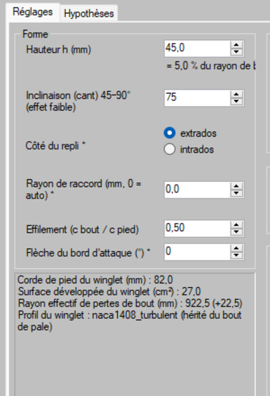
The shape of the winglet
4: The sections and the aerofoil
The Sections group sets how many calculation elements are devoted to the winglet — too few and the transition is coarse; too many and you take definition away from the rest of the blade. The Airfoil group gives the winglet its own section, which has no reason to be the one at the blade tip; Inherit the blade-tip airfoil keeps it identical when that is what you want.

Sections and aerofoil
5: Reading the assumptions
The Assumptions tab shows the tip loss model used. That paragraph is the most important of the window: it states what the calculation assumes, and therefore what the result is worth. A tip loss model is a correction of blade element theory, not a three-dimensional simulation of the tip vortex: it gives a reliable trend, not the certainty of a test.
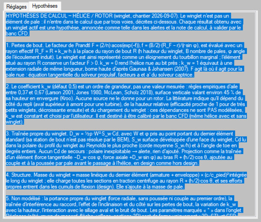
The model applied, stated
6: Check — geometry, then performance
Rebuild the 3D prototype: the blade tip must be clean, with no crossing facet. Then compare the performance with and without the winglet, at the same operating point.
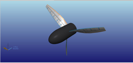
Without winglet
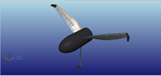
With winglet
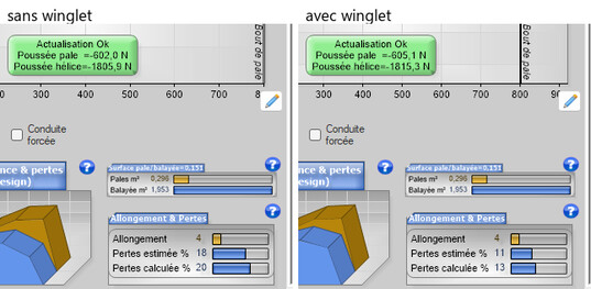
The balance sheet, at the same operating point
The winglet is carried by the 3D exports: what you see is what you will manufacture. For the other answer to the same problem, see the propeller duct.
 Global site map
 Mecaflux
 Tutorials Mecaflux Pro3D
 Tutorials Heliciel
 Tutorials Heliciel PRO CFD
 Mecaflux Store
 Compare software functions
 Quotes, Orders, Payment Methods
 project technical studies