
The same rotor geometry does not give the same performance depending on the environment declared. Here is which one to tick, and why.
Free stream, ducted propeller, ducted flow: the three calculation environments
A propeller never works "in general": it works in open air at the nose of an aircraft, inside a thruster nozzle, or in a closed duct. These three situations are not computed the same way, and Heliciel therefore asks you to declare which one is yours. It is probably the setting that, wrongly set, distorts the greatest number of projects.
- Tutorial outline:

The three environments are declared in the same place
1: Free stream
This is the general case: the aircraft propeller, the boat propeller, the wind turbine, the river hydro turbine. The calculation accounts for the axial and tangential inductions — the fluid is accelerated and set into rotation before it even reaches the blade — and counts the tip vortex losses, the fluid spilling around the end of the pressure side towards the suction side.
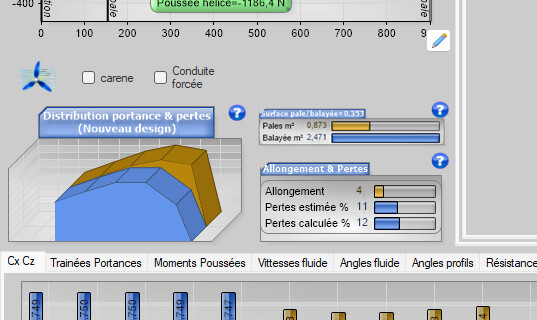
The free stream calculation
2: The ducted propeller
A duct fitted to the blade tip suppresses the spill: Heliciel then cancels the tip losses. This is the case of the ducted fan, of the thruster in its nozzle, of the wind turbine with a diffuser. The gain is real — it comes from the blade working right out to its end — but it has a price that the propeller-alone calculation does not see: the drag of the duct itself, and the sensitivity to the blade tip clearance.
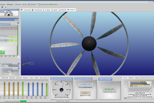
Ducted propeller: the tip losses are cancelled
3: Ducted flow
The third environment is the least known, and it is the one of circuit machinery: the in-duct fan, the propeller pump, the propeller or Kaplan turbine in a penstock. Here the flow rate is not the result of an induction, it is imposed by the circuit: Heliciel therefore takes the axial induction as zero.
What changes then is the question being asked:
- for a pump or a fan: what pressure rise must the rotor produce at the required flow rate;
- for a turbine: what head is available, and what can be drawn from it at the available flow rate.
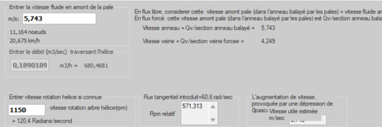
Ducted flow: the flow rate is an input, not a result
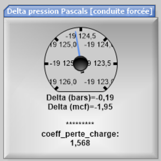
Pressure rise to produce, or head available
4: Comparing on the same geometry
The most instructive exercise takes three calculations: take a rotor, compute it in free stream, then ducted, then in ducted flow, changing nothing else. The three results differ — and the gap is not a display detail: it is the difference between three physics.
5: Frequent mistakes
- computing an in-pipe turbine as a free stream hydro turbine: the rotor is credited with an induction that does not exist, and both flow rate and power come out wrong;
- computing an in-duct fan as a plain ducted propeller: the tip losses are indeed cancelled, but the flow rate stays free while the circuit imposes it;
- forgetting that the duct drags: the efficiency of the propeller is not that of the assembly.
Going further: the propeller duct, the in-duct fan tutorial, the axial pump tutorial and the Kaplan turbine tutorial (these three tutorials are in French).
 Global site map
 Mecaflux
 Tutorials Mecaflux Pro3D
 Tutorials Heliciel
 Tutorials Heliciel PRO CFD
 Mecaflux Store
 Compare software functions
 Quotes, Orders, Payment Methods
 project technical studies