
Arms, base, motors, onboard modules: the multirotor project computes the whole assembly, and shows what tilting the frame costs in thrust.
Multirotor and VTOL project: sizing the complete craft
A drone propeller can be computed perfectly well on its own — Heliciel does that in its main interface. But a multirotor is not a propeller: it is four, six or eight rotors carrying a structure that has its own mass and its own drag, and that tilts in order to move forward. The multirotor project deals with that assembly.
- Prerequisite: an air propulsion propeller project open — it is the one that supplies the blade of the rotors;
- What you get out of it: a mass budget, an available thrust, a maximum horizontal speed and the pitch angle that gives it.
- Tutorial outline:
- Opening the multirotor project
- Project type and number of arms
- The geometry of the propellers
- The frame: base, arms, motors, loads
- The onboard modules
- Pitch angle and maximum speed
- Reading the forces on the 3D view
1: Opening the multirotor project
Files menu > Multi Rotors project. The window takes over the propeller of the current project: everything you have designed on the blade side — sections, chords, twist — becomes the blade of the rotors.
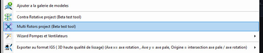
The menu entry
2: Project type and number of arms
The Multi Rotor Project tab carries the choice of the project family and the number of arms (Nb Arms). Quadcopter, hexacopter, octocopter: the number of rotors changes the available thrust, the structural mass and the redundancy, not the way the blade is computed.
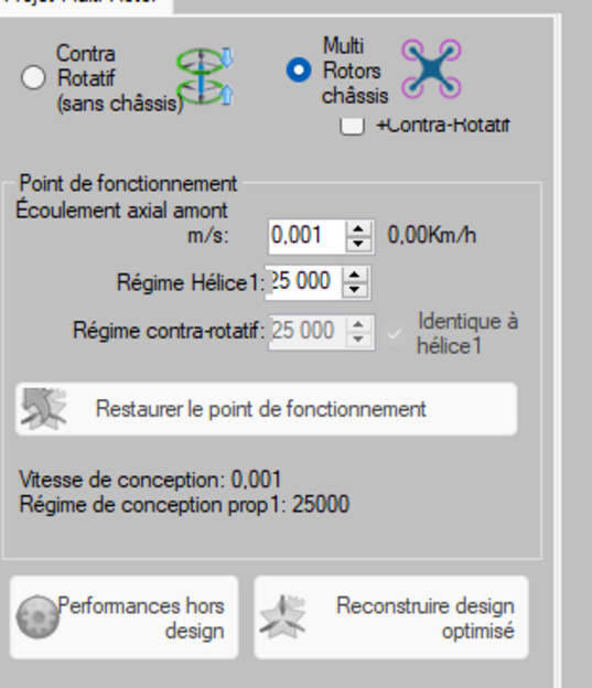
The project type and the number of arms
3: The geometry of the propellers
Propellers Geometry tab: diameter, number of blades, rotation speed. This is where the classical multirotor compromise is settled — a large slow rotor lifts better than a small fast one, but it takes more room and reacts more slowly.
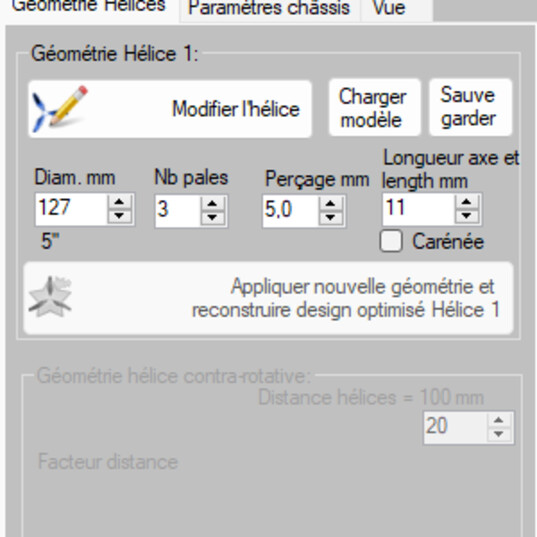
The geometry of the rotors
4: The frame — base, arms, motors, loads
Frame settings tab. Four groups, and each one weighs:
- Frame Base: the central plate;
- Arms geometry: length and section — they fix the spacing of the rotors and bring their own drag;
- Motors: KV constant, number of battery cells, weight of the motors;
- Frame loads: the arms + frame weight, kept up to date as you build.
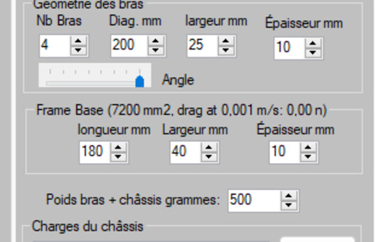
The frame is described, and its mass is counted
5: The onboard modules
A module is a mass the craft has to carry: battery, flight computer, gimbal, parcel. You add it with Add module, name it, give it its mass and a colour to spot it on the 3D view. The sum of the modules and of the structure is what the rotors have to lift: that is the real specification of the sizing.
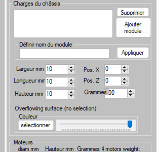
The onboard modules and the mass budget
6: Pitch angle and maximum speed
A multirotor moves forward by tilting: part of the thrust then goes to overcoming drag, the other part to holding the mass up. The Frame Pitch angle tests group deals with exactly that split. Two commands:
- Max horizontal speed at pitch 0°: the reference case, frame level;
- Find Max flyable Horizontal speed pitch: Heliciel sweeps the angles and keeps the one giving the greatest horizontal speed, displaying the horizontal and vertical projections of the speed.
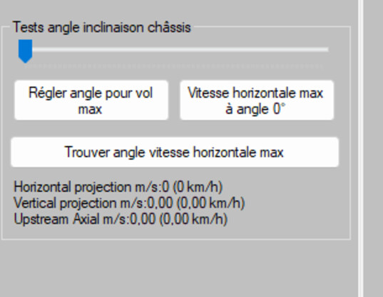
The angle sweep: what tilting brings in, and what it costs
7: Reading the forces on the 3D view
The View tab serves for checking as much as for illustration: force vectors at an adjustable scale, induced velocities, upstream and downstream flow particles, rotation speed of the animation. It is the picture to put in a file, and it is also the quickest way to see that one rotor is working in the wake of another.
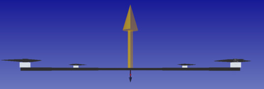
Forces and flow on the complete craft
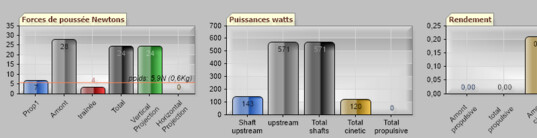
The result: masses carried, thrust, maximum speed
Going further: the drone propeller tutorial (the blade alone, in French), the contra-rotative project, and the presentation page of VTOL drone propellers.
 Global site map
 Mecaflux
 Tutorials Mecaflux Pro3D
 Tutorials Heliciel
 Mecaflux Store
 Compare software functions
 Quotes, Orders, Payment Methods
 project technical studies