
Turbine type, volute, distributor, draft tube, piezometric line: the tool sizes the hydraulic machine in which the propeller works.
The owner of an old mill has a water intake in a pipe: a net head of 2.5 m (after deducting the losses of the headrace and of the downstream draft tube) and a design flow of 120 l/s (0.12 m³/s). The goal is to equip the site with a small propeller turbine of the Kaplan type, starting from the Kaplan model supplied with Heliciel (238 mm runner, 6 blades, generator at 1,150 rpm).
This tutorial covers the concepts specific to turbines in a pipe: a wind turbine or a tidal turbine is sized by the speed of the fluid, whereas a turbine in a penstock is sized by the head (a pressure) and the flow (a velocity). Mixing up the two is the classic mistake, and Heliciel is equipped to avoid it.
- Outline and design steps:
- The Kaplan model and the penstock
- Turning the head into a pressure, never into a velocity
- Turning the flow into a velocity in the pipe
- The design point and its geometry
- The head / runner balance
- Summary and model to download
- Beyond the runner: designing the whole installation
1: The Kaplan model: the supplied model is a 238 mm runner with 6 blades of very high solidity (chords reach 119 mm at the tip for a radius of 119 mm!). This is the signature of turbines in a pipe, where the runner must "close" the passage to convert the pressure. The penstock mode is active: the stream is imposed by the pipe, the flow does not expand, and tip losses are cancelled by the small clearance.
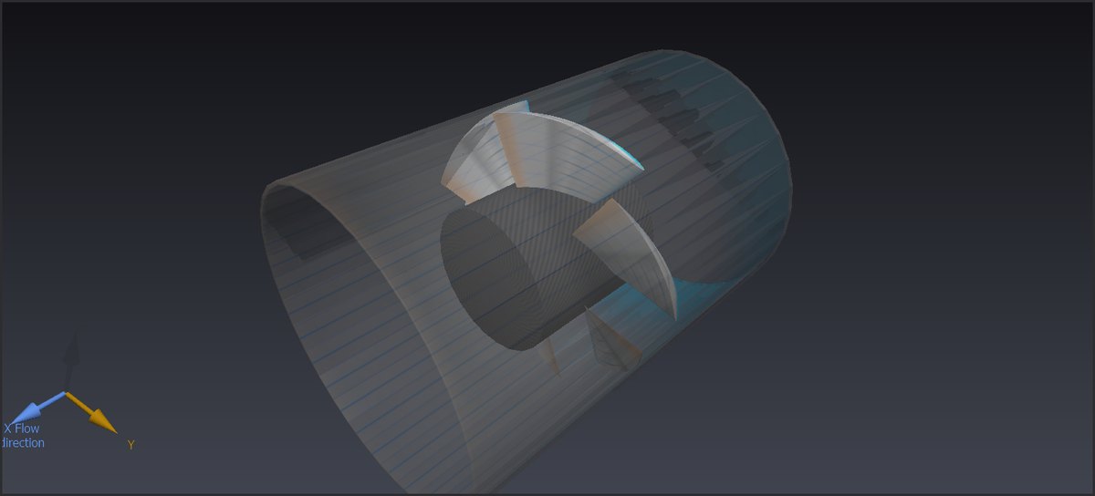
The 238 mm runner in 3D, three-quarter view inside its penstock (shown transparent): six wide blades on a large 121.4 mm hub, which takes up half of the diameter.
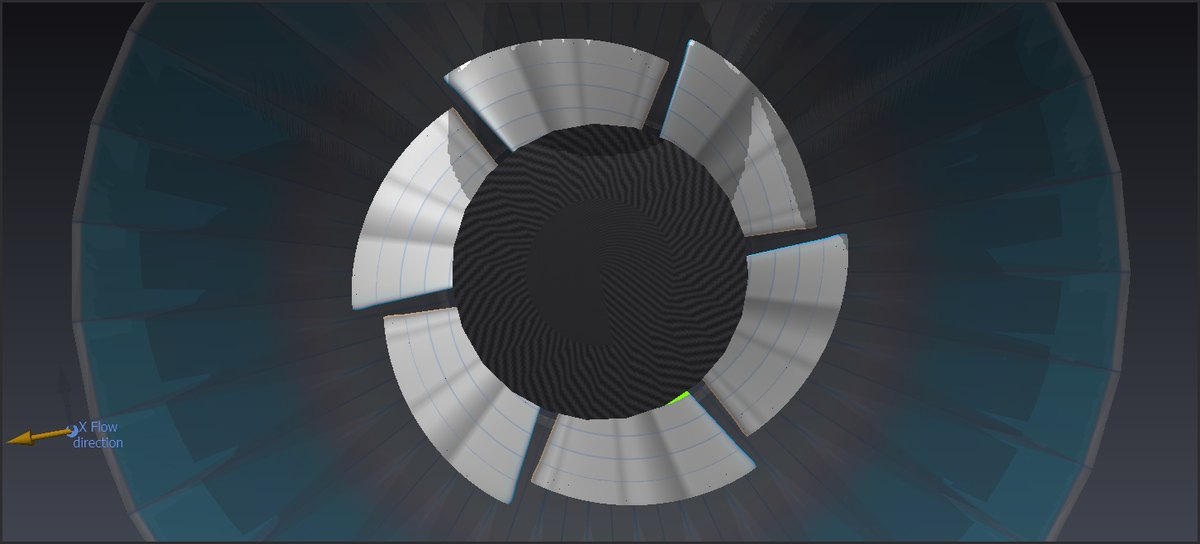
Axial view: the six blades cover the annular section between hub and pipe, leaving only narrow slots between them. This high solidity is what allows the runner to convert the pressure of the head.
2: The head is a pressure: 2.5 m of net head translate into ΔP = ρ·g·H = 999.7 × 9.81 × 2.5 = 24,510 Pa available to the runner. Heliciel writes this reference pressure in the "Delta pascals" box of the project. Two traps the software helps you avoid:
- NEVER convert the head into a velocity with Torricelli's formula (v = √2gH): it describes a free jet, not a pipe under pressure;
- the GROSS head of the site is not the head of the runner: the upstream pipe and the downstream draft tube consume part of it. Enter the NET head (or the gross head and the losses, and Heliciel subtracts them).
3: The flow is a velocity: the annular passage section (238 mm runner, 121.4 mm hub) is S = 0.0329 m². Our 120 l/s therefore flow through it at v = Q/S = 3.65 m/s. Heliciel makes this conversion when it is given the flow: the velocity is not a figure to be invented.
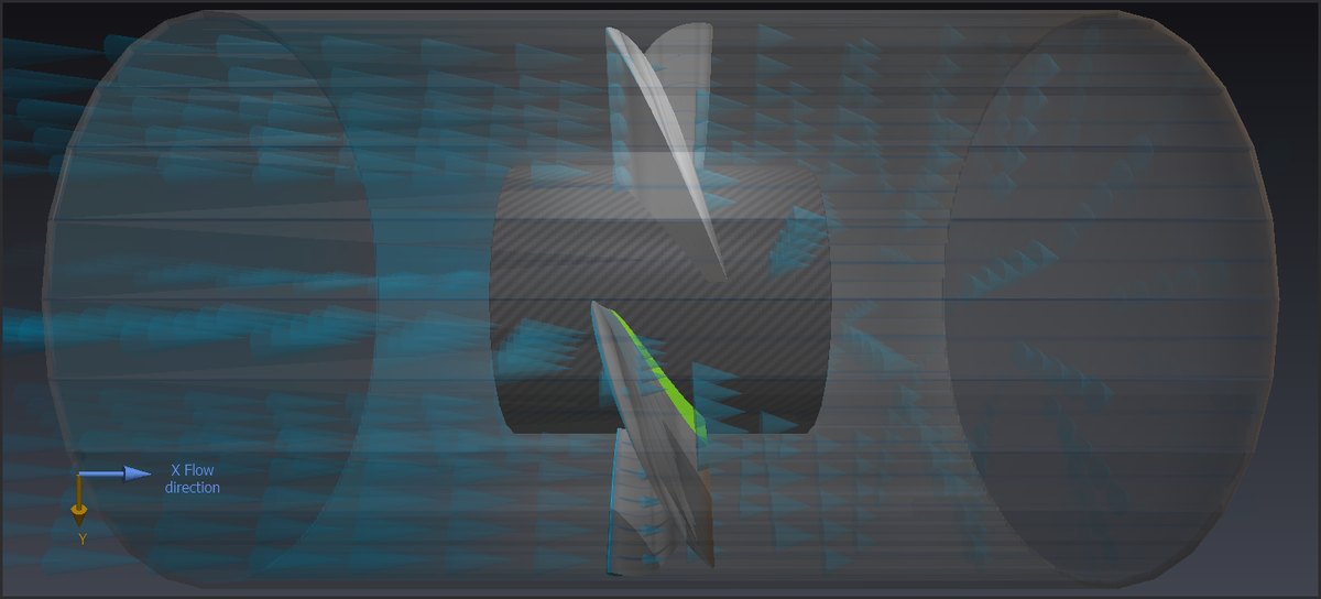
The velocity particles flow through the runner. In a penstock the stream does not expand: the pipe sets the section, and therefore the mean velocity Q/S.
4: The design point: we run the turbine design at a flow of 0.12 m³/s, with the generator at 1,150 rpm. Heliciel rebuilds the optimum twist and returns:
- shaft power: 2,736 W, torque +22.7 N·m (positive: the machine produces power; Heliciel's sign convention tells the nature of the machine);
- blade pitch angles from 34.6° at the root to 20.7° at the tip, the typical twist of a Kaplan runner;
- axial thrust on the runner: 462 N (to size the thrust bearing!);
- no computation error, and one warning worth knowing: the solidity is high in a penstock (σ = 1.01 at the root, where the spacing between blades is smaller than the chord), a range in which the isolated-airfoil polars used by the computation are an approximation.
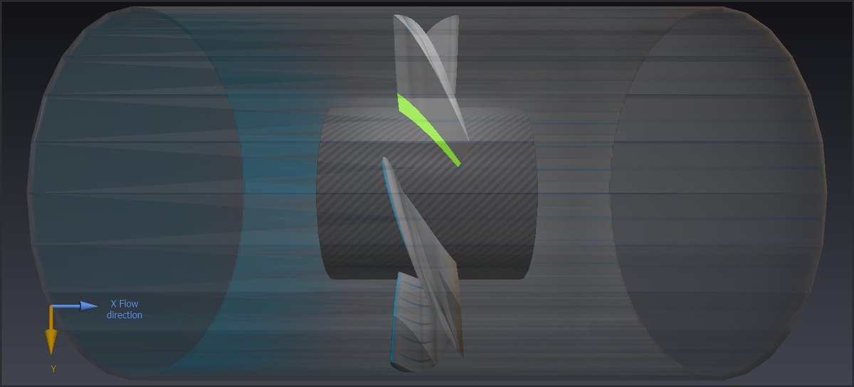
Side view of the runner, water flowing from left to right: the twist of the blades shows on the lower ones. The pitch angle goes from 34.6° at the root to 20.7° at the tip: this is the twist the design rebuilt for this operating point.
5: The head / runner balance: this is what is specific to projects in a pipe in Heliciel. The design result carries three fields to be read together:
- available head: 2.50 m (our input);
- head consumed by the runner: 1.43 m (the pressure drop the runner creates at this point: 14,040 Pa);
- exploited head ratio: 0.57, with the associated alert: "The runner only uses 57.3% of the available head (gap > 10%): part of the net head is not converted. Options: reduce the speed, or increase the pitch or the solidity".
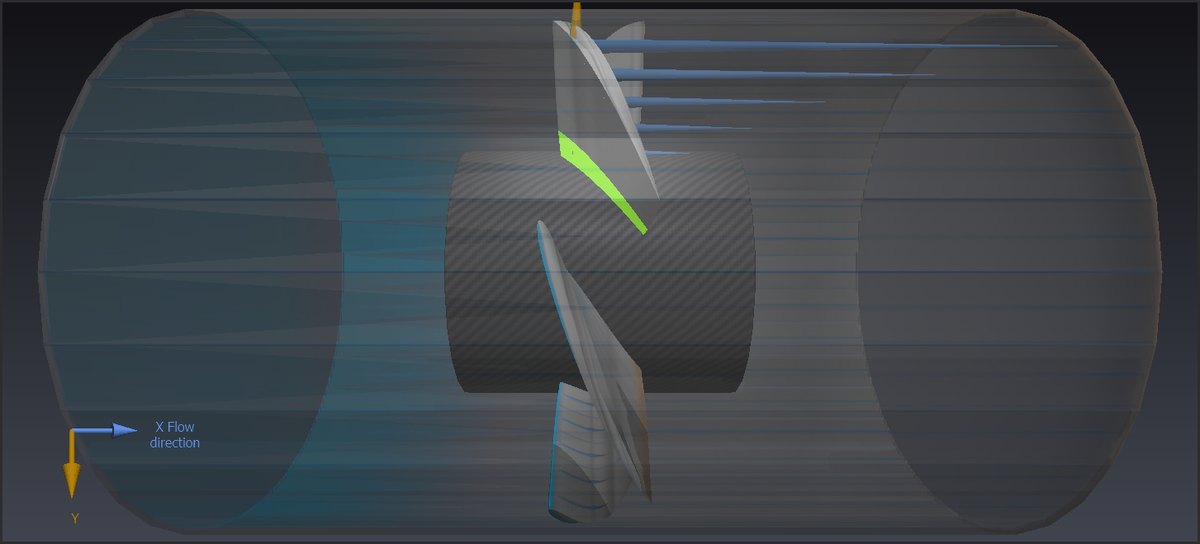
The blue arrows give the axial thrust of each blade element, pointing downstream and stronger towards the tip. Divided by the passage section, the total thrust (462 N over 0.0329 m²) matches the 14,040 Pa of head consumed by the runner.
Understanding this balance is THE know-how of turbines in a pipe: if the runner consumes less than the head (ratio < 1), the actual operating point will drift (higher flow, different speed) until it balances; if it demands more (ratio > 1), the flow will drop. Balancing is worked out by iterations: speed (the search for the speed matching the head sweeps the speeds on the frozen geometry), blade pitch (a real Kaplan has adjustable blades!), solidity, or even diameter. Each trial is judged on this ratio and on the hydraulic efficiency. We ran several of these iterations during the study: remember that the model runner, with its very high solidity, is cut for heads higher than 2.5 m at full load, and that at 120 l/s it leaves some potential. A real site would arbitrate between increasing the design flow and accepting this gentle operation. The fine validation of these flows in a pipe (including the swirl of the distributor) then belongs to the CFD module of Heliciel, which meshes and simulates the complete case.
6: Summary and model to download
- Micro Kaplan Ø 238 mm, 6 blades, 121.4 mm hub, in a penstock;
- design point: 120 l/s at 1,150 rpm under 2.5 m net head, 2,736 W at the shaft, torque 22.7 N·m, axial thrust 462 N;
- head consumed by the runner 1.43 m (ratio 0.57): the site leaves room for more equipment;
- the three reflexes: head → pressure (ρgH); flow → velocity (Q/S); read the exploited head ratio.
The complete project can be downloaded here: micro_kaplan_238mm_120ls.hlc (to be opened with Heliciel). It is also among the models supplied with the software. See also the small hydro plant design tutorial.
7: Beyond the runner: designing the whole installation with Hydro Turbine design
This tutorial worked on the runner alone, with a net head and a flow set by hand. On a real site these two figures are not given: the net head depends on the losses of the penstock, the spiral casing, the distributor and the draft tube, and the flow depends on the balance between the head and the runner. A Kaplan turbine is a machine with four components: a spiral casing (volute) that sets the water in rotation, a distributor with adjustable guide vanes that controls the flow and gives the stream its swirl, the runner, and a draft tube that recovers the remaining head downstream.
This is the job of the Hydro Turbine design window of Heliciel: it designs the whole installation, distributor, volute and draft tube included, from a given site:
- you enter the site: gross head, maximum flow, penstock (length, diameter, roughness) and height of the runner outlet;
- Heliciel computes the specific speed, tells whether the site calls for a Pelton, a Francis or a Kaplan, and proposes the runner dimensions from the statistics of built turbines (ESHA, A. Tenot, Layman);
- it sizes the volute, the distributor (number, profile, height and opening of the guide vanes) and the draft tube, with the head loss of each component;
- its solver balances the runner on the head actually available, closes the Bernoulli balance of the stream (piezometric line from headwater to tailwater) and checks cavitation;
- it shows the installation in 3D, with the water trajectories, and provides the sheet-metal drawings of the gate ring, the guide vanes and the draft tube;
- the balanced runner is then sent to the Heliciel project, in penstock mode, with the swirl given by the distributor: this is where the work of this tutorial starts again.
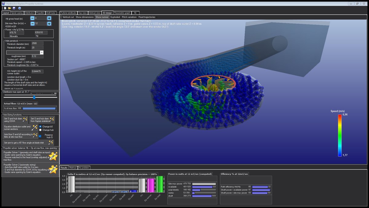
The Hydro Turbine design window on a 12 m³/s, 4 m head study: on the left the site, the tabs of the components (spiral casing, distributor, propeller, draft tube) and the sizing solvers; on the right the installation in 3D with the water trajectories coloured by velocity; at the bottom the balance of losses, powers and efficiencies.
Hydro Turbine interface of Heliciel (requires a Mecaflux Suite license)
Menu File > Hydro Turbine design, available on workstations where Mecaflux Pro3D is installed. Its complete user guide, tab by tab, is on the page Hydro Turbine design: sizing the structure around the Kaplan runner, illustrated with a site of 12 m³/s under 4 m of head.
For any comment or further information, contact me at contact@heliciel.com
- JF Iglesias, Heliciel developer.
 Global site map
 Mecaflux
 Tutorials Mecaflux Pro3D
 Tutorials Heliciel
 Tutorials Heliciel PRO CFD
 Mecaflux Store
 Compare software functions
 Quotes, Orders, Payment Methods
 project technical studies