
Small hydro plant design tutorial 1/3: the site, its power and the runner
This tutorial on designing a small hydroelectric plant sizes, in three parts, a Kaplan turbine for a site of 12 m³/s under 4 m of gross head, with the Hydro Turbine design workshop of Heliciel. This first part sets the site data, computes its power, chooses the turbine family by the specific speed and sizes the runner from statistics. The second part sets the distributor and the spiral casing, the third the draft tube, balancing and cavitation.
All the values in this tutorial are read in the Hydro Turbine design window, and each picture is the screen produced during the study. The 12 m³/s and 4 m site has been the one of this tutorial since its first version; the supply pipe (20 m, 2,500 mm) and the runner height are example choices, stated as such. The study (.hydt) and the project (.hlc) can be downloaded at the end of the third part.
Hydroelectric turbines chapter:
- Power capture with a Kaplan turbine 1/3: the components and how they work
- Power capture with a Kaplan turbine 2/3: the distributor-runner relationship
- Power capture with a Kaplan turbine 3/3: the design method
- Hydroelectric plant tutorial 1/3: site power and runner
- Hydroelectric plant tutorial 2/3: distributor and spiral casing
- Hydroelectric plant tutorial 3/3: draft tube, balancing and cavitation
Contents of this page:
- The site: flow rate, gross head and hydraulic power
- The layout in Heliciel: penstock and runner height
- The specific speed and the choice of rotational speed
- The runner from the Kaplan statistics and the ESHA formula
- What the runner expects from the distributor
1: The site: flow rate, gross head and hydraulic power
We are developing a site whose mean flow rate is 12 m³/s and whose usable gross head is about 4 m. The flow rate is measured from the flow velocity and the river section; one page gathers various methods for measuring the flow rate of a river. The head is created by a low diversion dam, for a run-of-river installation: concrete, wood or masonry, whose cost alone can decide the viability of the project. Propeller or Kaplan turbines are made for these low heads, but a minimum height is still needed to overcome the head losses and make the distributor and the runner work.
The gross hydraulic power is Q × H × ρ × g = 12 × 4 × 999.7 × 9.81 = 470,750 W, i.e. 471 kW at 10 °C. The head losses, then the runner and the generator, will each take their share; the electrical power divided by this gross power will be the overall efficiency of the plant.
2: The layout in Heliciel: penstock and runner height
We open Hydro Turbine design from the File menu of the designer. In the Implantation tab, we enter the gross head Hb = 4 m and the maximum flow rate 12 m³/s: Heliciel displays 470.75 kW gross.
The supply penstock is example data: 20 m long, 2,500 mm in diameter, roughness 0.12 mm. Heliciel derives a section of 4.9 m², a velocity of 2.45 m/s and a head loss of 0.027 m by the Colebrook formula. We chose this diameter to stay close to the velocity the spiral casing will require, 1.77 m/s for a cast iron casing: a narrower pipe would waste head for nothing.
The height H2 places the runner outlet above the tailwater level. We set it to 0.45 m, the lowest the geometry allows: Heliciel refuses a value lower than the bulb length. We will see in the third part that this choice governs cavitation. With this height and the draft tube length, Heliciel adds an elbow and a horizontal junction pipe to the flow path.
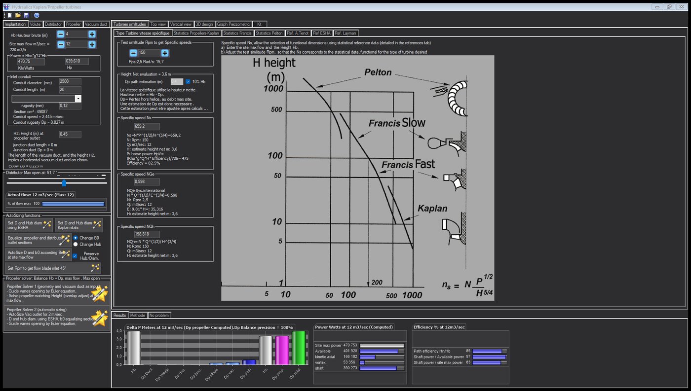
The Implantation tab: the site, the pipe, H2, and on the left the sizing functions we will use.
Hydro Turbine interface of Heliciel (requires a Mecaflux Suite license)
3: The specific speed and the choice of rotational speed
The Type Turbine vitesse spécifique tab computes Ns, NQe and NQh from the flow rate, an estimated net head (Hb minus 10 %, i.e. 3.6 m, to be readjusted later) and a trial speed. We adjust this speed until Ns enters the range of Kaplan turbines, 350 to 2,000 in the window. On this site, the range corresponds to speeds from 80 to 455 rpm.
We first tried 230 rpm, in the middle of the range (Ns ≈ 1,000): the runner was smaller and faster, and the third part will show that it cavitated. We keep 150 rpm, which gives Ns = 659: a slower, larger and better-behaved Kaplan. This trial speed becomes the runner speed as long as the Propeller tab stays in similarity mode.
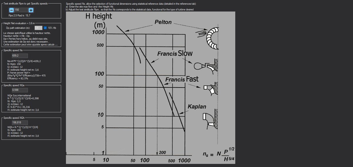
At 150 rpm, Ns = 659: the machine is a Kaplan, the chart confirms it.
4: The runner from the Kaplan statistics and the ESHA formula
The Statistics Propellers-Kaplan tab reads, for Ns = 659, the similarity factors of the fleet of turbines built: the peripheral speed factor ξ₁, the ratios b0/D1 and d/D1. From them it derives U1 = ξ₁·√(2·g·Hn), then D1 = 60·U1/(π·N), the height b0 and the hub. The table in the tab also suggests the number of blades according to Ns.
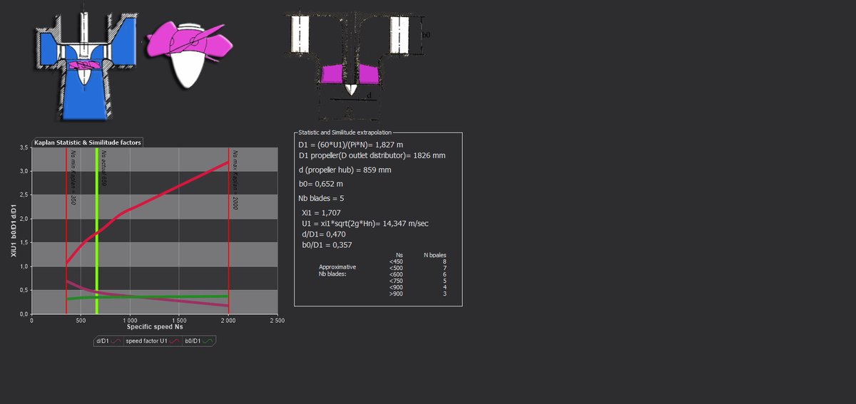
The Kaplan statistics at Ns = 659: the three factors, and the dimensions they give.
We let the solver apply the ESHA formula for the diameter and the hub, and the statistics for the number of blades: the runner is 1,868 mm, with a 766 mm hub (41 %), five blades, at 150 rpm. The swept section is 2.28 m² and the axial velocity, Q/S, 5.26 m/s. These dimensions are proposals: the radio buttons of the Propeller tab let you impose them.
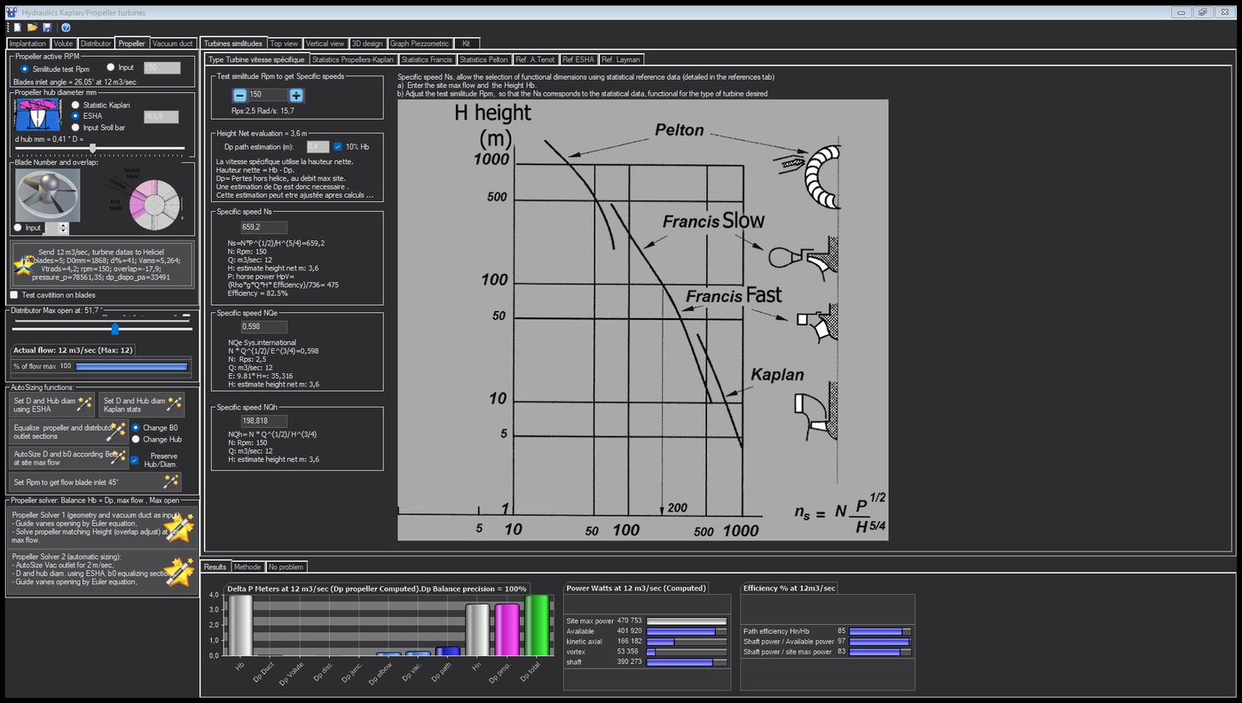
The Propeller tab: diameter and hub by ESHA, five blades, similarity speed. The chord overlap will be the balancing variable.
The blade overlap, as a percentage of the blade spacing, sets the width of the chords. It is what the solver will adjust, in the third part, so that the runner absorbs exactly the head that falls to it: a runner in a conduit must "block" the passage to the right degree, no more, no less.
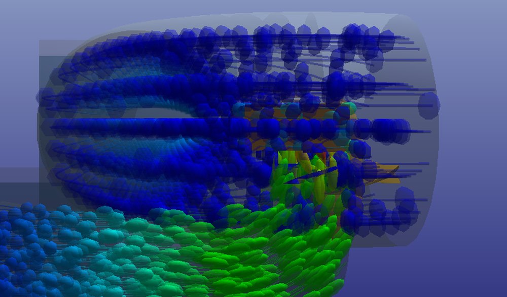
The runner in a dimensioned cut: the blades, the 766 mm hub, the bulb, and the particles flowing down from the runner to the draft tube.
5: What the runner expects from the distributor
The runner is set, but it does not turn on its own: it expects water under pressure, set spinning to the right degree, and a draft tube that lowers its outlet pressure. The distributor-runner relationship says why: the rotation given by the distributor is a share of the head, which the runner converts into torque by straightening the current.
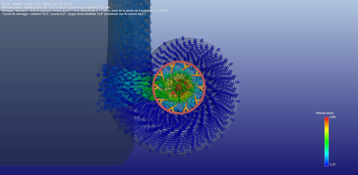
The example installation in 3D perspective: the spiral casing, the distributor, the runner, and the water trajectories coloured by velocity, blue in the spiral, green and yellow at the runner.
For a more modest site, such as a mill with a pipe of a few hundred litres per second, the 238 mm micro Kaplan turbine tutorial works on the runner alone in the Heliciel designer: head turned into a pressure, flow into a velocity, and the head / runner balance.
To go further, we move on to the design of the distributor and the spiral casing.
 Global site map
 Mecaflux
 Tutorials Mecaflux Pro3D
 Tutorials Heliciel
 Tutorials Heliciel PRO CFD
 Mecaflux Store
 Compare software functions
 Quotes, Orders, Payment Methods
 project technical studies