
Small hydro plant design tutorial 2/3: the distributor, the spiral casing and the runner
The distributor of a Kaplan turbine converts a share of the head into rotation of the water before the runner, and regulates the flow rate by the opening of its guide vanes; the spiral casing brings it the water already spinning, at constant velocity all around. This second part of the hydroelectric plant tutorial sizes both components for the 12 m³/s site under 4 m, in Hydro Turbine design, and reads the rotation they give to the 1,868 mm runner set in the first part.
Hydroelectric turbines chapter:
- Power capture with a Kaplan turbine 1/3: the components and how they work
- Power capture with a Kaplan turbine 2/3: the distributor-runner relationship
- Power capture with a Kaplan turbine 3/3: the design method
- Hydroelectric plant tutorial 1/3: site power and runner
- Hydroelectric plant tutorial 2/3: distributor and spiral casing
- Hydroelectric plant tutorial 3/3: draft tube, balancing and cavitation
Contents of this page:
- The spiral casing: material, velocity and sections
- The distributor geometry: guide vanes, height b0 and axis circle
- The guide vane opening and the swirl given to the runner
- The head losses of the distributor
- A pitfall: guide vanes inside the runner
- For the record: computing a ring distributor as a stator
1: The spiral casing: material, velocity and sections
In the Volute tab, we choose a cast iron casing. Heliciel proposes the matching admissible velocity, Ve ≤ 0.2·√(2·g·Hn), i.e. 1.77 m/s at maximum flow, and derives the inlet diameter, 2,937 mm. It then computes the eight sections S1 to S8 of the spiral, which keep this velocity all around the distributor, and the angle at which the water meets the guide vanes. Riveted sheet metal and concrete have their own, lower, velocities: concrete erodes above 3 m/s.
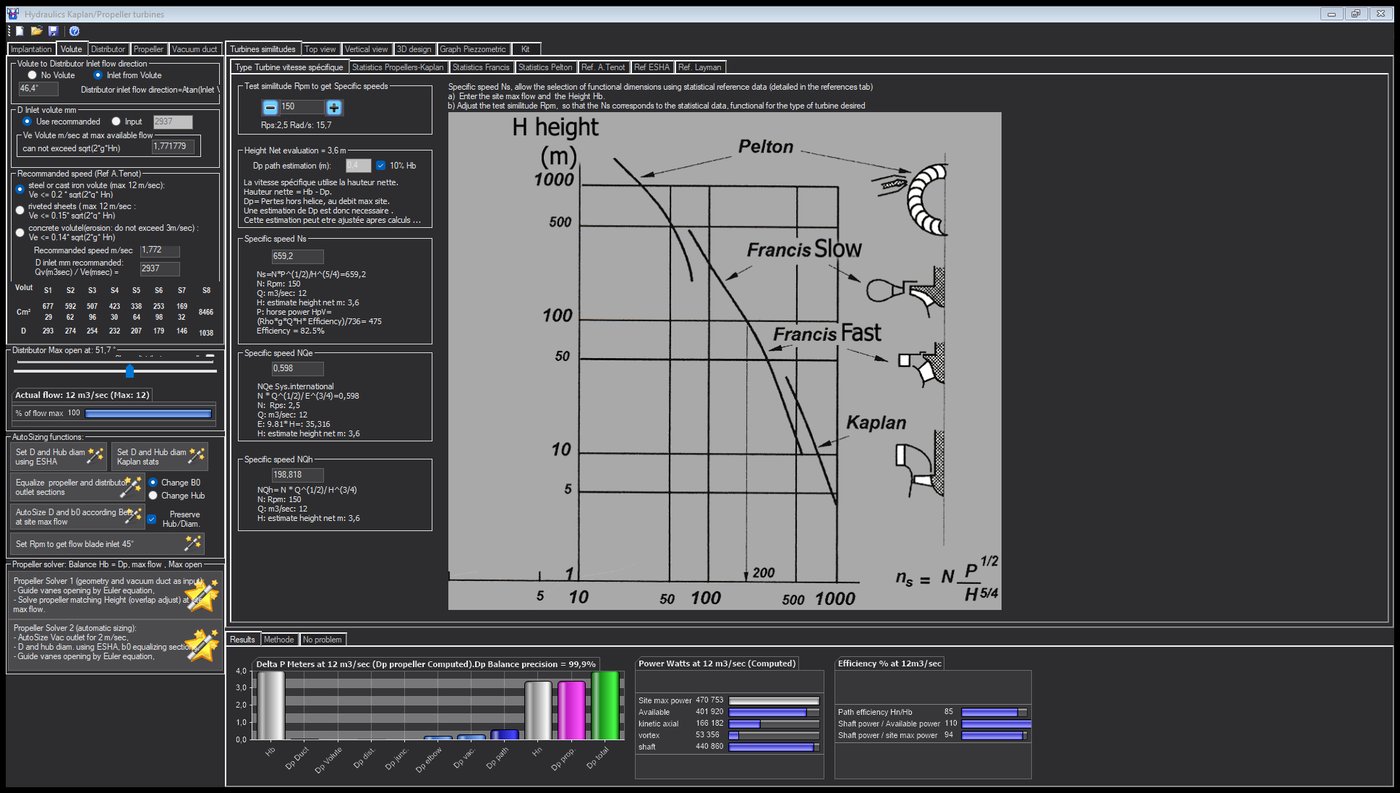
The casing of the example: cast iron, 1.77 m/s, and the eight sections of the spiral.
Hydro Turbine interface of Heliciel (requires a Mecaflux Suite license)
2: The distributor geometry: guide vanes, height b0 and axis circle
The Distributor tab carries the distributor outlet diameter, equal to the runner diameter, 1,868 mm by ESHA. We keep ten guide vanes, a thin NACA profile with little camber (thickness 10 %, camber 2 %), and we let the solver set the two other dimensions:
- the height b0 of the guide vanes, by equalizing the distributor outlet section with the annulus swept by the runner, b0·π·D = π·(D² − d²)/4: 652 mm;
- the diameter of the axis circle of the guide vanes, 1.2 D by default, which the solver raised to 2,508 mm to reach the required swirl.
Both remedies are announced by the solver in its final message: "distributor height b0 raised from 388.5 to 651.8 mm; axis circle raised from 2,242 to 2,508 mm". Nothing is changed silently.
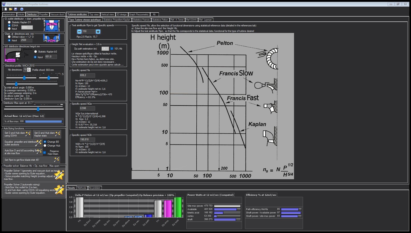
The distributor of the example: ten guide vanes, b0 652 mm, axis circle 2,508 mm, opening 51.7°.
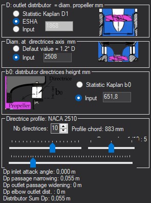
The distributor panel: D by ESHA, axis circle, b0, NACA 2510 profile of the ten guide vanes, and the four loss terms, 0.055 m in total.
3: The guide vane opening and the swirl given to the runner
The guide vane opening sets the swirl. The distributor-runner relationship showed it: for the runner to straighten the water and absorb its head, the angular momentum to give it is K = g·H_runner / ω. The solver searches for the opening that produces it, by bisection on the slider: 51.7° on the example, i.e. the contact stop with the runner at this geometry, for a circulation constant K of 2.49 m²/s. In the top view, Heliciel displays the equivalent rotation sent to the runner, 4.18 rad/s, and the kinetic powers at the runner inlet: 166 kW axial, 53 kW tangential.
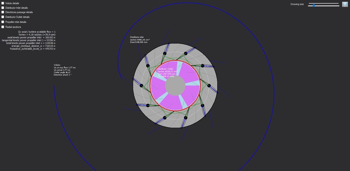
The top view: the spiral, the ten guide vanes and the swirl they produce.
These 53 kW are not a loss: they are the share of the head that the distributor has turned into rotation, 0.45 m of swirl head, and that the runner will convert into torque. The sign of it is the runner outlet tangential velocity returned by the runner calculation: 0.07 m/s for 2.98 m/s at the inlet, the water leaves straightened.
For the order of magnitude, the guide vane angle can be found by hand: for a distributor with a spiral casing, tan(angle) = axial velocity / tangential velocity at the passage. Heliciel displays both velocities at the guide vane passage in the top view, with details ticked.
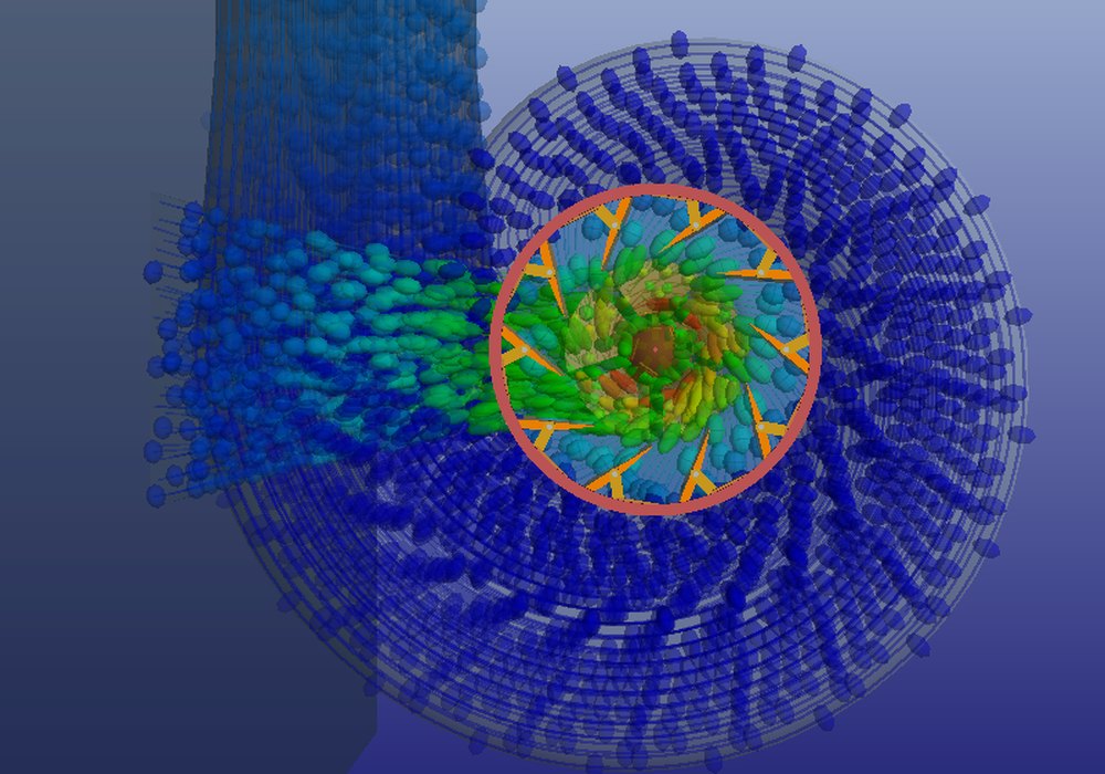
Close-up of the distributor: the gate ring, the guide vanes and the water particles, blue in the casing, green and yellow as they accelerate towards the runner.
4: The head losses of the distributor
Heliciel computes the distributor loss in four terms, after Idel'cik: the angle of attack at the guide vane inlet, the narrowing of the passage between them, the expansion at the outlet and the elbow towards the runner. With ten guide vanes open at 51.7° and a casing that brings the water at the right angle, the total is 0.055 m, mostly the narrowing of the passage. A distributor without a spiral casing, which would have to deflect the water by 60° on its own, would cost several meters: the casing is not a luxury.
The pipe adds 0.027 m. The complete balance, with the elbow and the draft tube, will come in the third part.
5: A pitfall: guide vanes inside the runner
Our first attempt is instructive. The window had kept, in user-set mode, the axis circle of a micro-turbine: 594 mm. For a 1,574 mm runner, the guide vanes were inside the runner, the passage between them measured 0.41 m² and the water ran through it at 28.9 m/s: negative pressure at the passage, cavitation of the flow path and of the blades. Putting it back in default mode, 1.2 D, restored everything. The piezometric graph flags this kind of error at a glance: a pressure that dives below the vapor pressure at one point of the flow path. Before reading an efficiency, always check that every dimension is in the intended mode.
6: For the record: computing a ring distributor as a stator
Before Hydro Turbine design, we computed a bulb-type ring distributor in the designer itself, as a propulsion propeller that does not turn: twelve blades with a cambered NACA 6412 profile, speed of 0.01 rpm to simulate standstill, angles of attack forced to the angle of maximum lift, and we read the tangential velocity produced downstream and the pressure loss across it. This route remains open, and it is the one followed by the export of a stator to Mecaflux Pro3D. The head loss of a blade cascade can also be computed in Mecaflux, singular losses, "profile cascade" element. Hydro Turbine design does both calculations in its place, with the spiral casing on top.
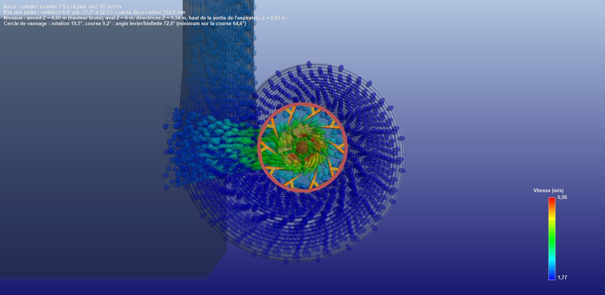
The example installation in 3D perspective: the spiral casing, the distributor, the runner, and the water trajectories coloured by velocity, blue in the spiral, green and yellow at the runner.
For a more modest site, such as a mill with a pipe of a few hundred litres per second, the 238 mm micro Kaplan turbine tutorial works on the runner alone in the Heliciel designer: head turned into a pressure, flow into a velocity, and the head / runner balance.
To go further, we move on to the third part: the draft tube, balancing and cavitation.
 Global site map
 Mecaflux
 Tutorials Mecaflux Pro3D
 Tutorials Heliciel
 Tutorials Heliciel PRO CFD
 Mecaflux Store
 Compare software functions
 Quotes, Orders, Payment Methods
 project technical studies