
Does the flow get through? CFD answers with the pressure all along the duct.
Ducted fan CFD, blowing on a radiator: who wins, the fan or the exchanger?
Fan and CFD: this is the problem of every cooling system designer: a fan, a duct, a finned heat exchanger. The fan pushes, the exchanger brakes. The flow rate that really gets through is the outcome of this tug of war, and no data sheet gives it, since each sheet describes its component alone. This case study puts both in the same duct and lets the CFD (Computational Fluid Dynamics, numerical simulation of the flow) bench decide. The radiator is a simple STL file dropped into the domain: any object from your CAD can take its place.
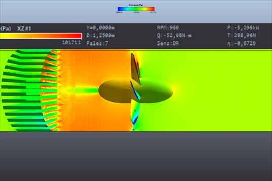
The pressure cut along the axis of the duct tells the whole story: the air arrives from the right (green), the fan compresses it (orange), the finned radiator relaxes it (back to green). The banner at the top recalls the speed, power, torque and thrust of the computation.
- Contents:
- The installation
- The CFD of a ducted fan: a heavier computation than a free propeller
- The pressure along the duct
- The fan flow rate in CFD, and the verdict
- The velocity between the fins
- Take-aways
1: The installation
| Fan | 7 blades, diameter 1.25 m, hub ∅ 0.40 m, 960 rpm (64 m/s at the blade tip) |
| Duct | cylindrical, inner diameter 1.30 m, fully guided flow |
| Radiator | finned exchanger (STL file), placed 1.5 m downstream of the fan, across the whole section |
| Air | 1.3 kg/m³ (cold air), mean velocity 12.3 m/s in the duct |
| Heliciel designer (BEM) | 479 N of thrust, 75 N·m of torque, fan alone |
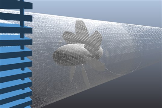
The case as built in the bench: the duct (white wireframe), the fan in the centre, and on the left the blue fins of the inserted radiator. The object was positioned in the Insert tab, with the mouse or by giving its position in metres.
2: The CFD of a ducted fan: a heavier computation than a free propeller
A closed duct costs more than a rotor in open air: the air must be described everywhere between the fan and the wall, and the radiator fins multiply the surfaces. The Duct Level 3 preset produced 6.5 million cells in 4 h 35 on a 6-core desktop PC, and the first phase of the computation took 18 minutes. It is an overnight computation, not a coffee-break one; the bench announces it beforehand in its estimate, next to the preset list, and a Duct Level 1 would have given a first overview in ten times less time.
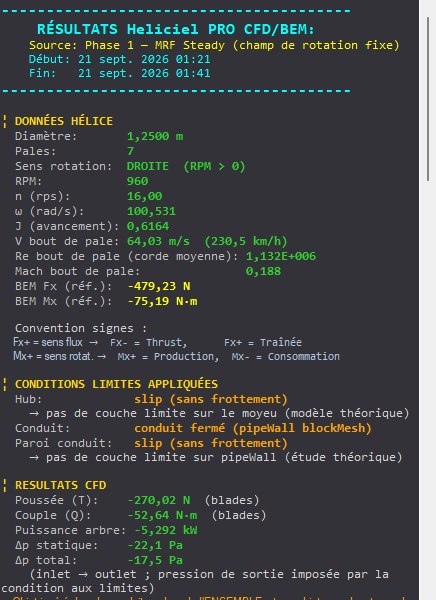
The results panel. Besides thrust and torque, a closed duct brings up two lines that do not exist for a free propeller: the pressure change between the inlet and the outlet of the duct, and the flow rate. The panel also recalls that the duct wall and the hub are treated without friction, a choice of the preset.
3: The pressure along the duct
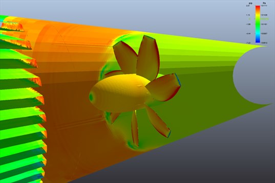
The pressure coloured on all the walls. The duct is green on the right (drawn-in air, slightly low pressure), orange between the fan and the radiator (the compressed air waiting to cross the fins), then green again on the left, after the radiator. The radiator itself is green: it is what consumed the overpressure.
The reading is that of a pressure gauge walked along the duct. The fan raises the pressure; the radiator brings it back down. What CFD adds to the reasoning is the value and the distribution: the overpressure is not uniform over the section, it is stronger towards the wall than in the centre, behind the hub.
4: The fan flow rate in CFD, and the verdict
| Mass flow rate (duct inlet and outlet) | 21.1 kg/s, conserved to within 0.03 % |
| Volume flow rate at 1.3 kg/m³ | 16.3 m³/s |
| Static pressure change, inlet → outlet | −22 Pa |
| Total pressure change, inlet → outlet | −17 Pa |
| Fan thrust, CFD | 289 N (designer: 479 N) |
| Shaft power, CFD | 5.3 kW |
The sign is the verdict. Between the inlet and the outlet of the duct, the pressure drops by 22 Pa: the radiator holds back a little more than the fan pushes. The bench says it itself in its result note: "a negative Δp means that the object holds back more than the rotor pushes, not that the rotor lowers the pressure". Concretely, this fan, at this speed, is not quite enough to push 16 m³/s through this exchanger in a straight duct: either a little more speed, or a less dense exchanger, or a lower flow rate to accept. This is exactly the question a design office asks itself, and the answer is one signed number.
Two remarks to read this number correctly. The outlet pressure is the one imposed at the end of the duct, it is not measured: the Δp is therefore relative to that outlet. And since the duct wall is frictionless in this preset, the Δp does not contain the pressure loss of the shell itself, which a classical pipe calculation adds without difficulty.
The CFD thrust of the fan (289 N) is well below the designer's (479 N): the radiator downstream changes the operating point of the fan, which no longer works in the conditions it was drawn for. This is a result of the installation, not an error of either.
5: The velocity between the fins
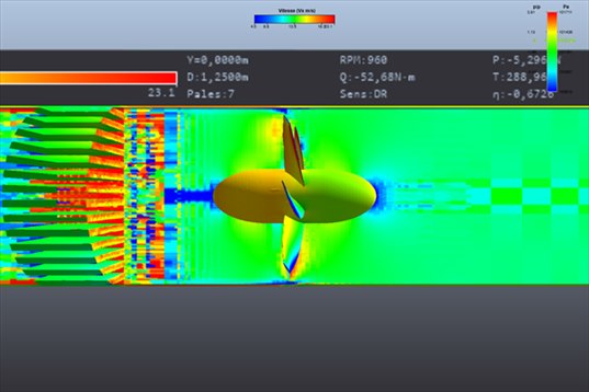
The same cut, coloured by velocity. Between the radiator fins, on the left, the air accelerates (red streaks): the passage section is reduced. It is this acceleration, then the slowdown that follows, that costs the pressure. At the blade tips, the blue and red patches are the fan jet seen in cross-section.
6: Take-aways
- An object from your CAD is dropped into the domain as STL, and CFD computes the complete system, not the separate components.
- The verdict is one signed number: the pressure change between the inlet and the outlet of the duct, here −22 Pa. Negative, the exchanger wins; positive, the fan has margin.
- The real flow rate is 16.3 m³/s, conserved to within 0.03 % between inlet and outlet: CFD does not lose air along the way.
- A closed duct is a heavy computation: 6.5 million cells and a night of meshing at Level 3. Start at Level 1, read the estimate before launching.
The CFD case studies
« Previous: Tidal turbine CFD: a 16 m rotor in the current | Next: Wing CFD and hydrofoil: lift and drag »
- Understanding a CFD result in five pictures
- Boat propeller CFD: thrust and pressure on the blades
- Aircraft propeller CFD: cruise and static thrust
- Drone propeller CFD: hover
- Wind turbine CFD: power and wake
- Tidal turbine CFD: a 16 m rotor in the current
- Ducted fan CFD: duct and radiator (you are here)
- Wing CFD and hydrofoil: lift and drag
These case studies complement the Heliciel design tutorials (in French), which cover the BEM side: blade design, choice of speed, performance curves. To go further into the method, the technical collection of twenty tutorials remains available.
 Global site map
 Mecaflux
 Tutorials Mecaflux Pro3D
 Tutorials Heliciel
 Mecaflux Store
 Compare software functions
 Quotes, Orders, Payment Methods
 project technical studies