
Hydraulic energy capture by Kaplan turbine 2/3: the relation between distributor and runner
The relation between the distributor and the propeller of a Kaplan turbine comes down to one idea: the distributor takes a share of the head to set the water in rotation, and the runner recovers this rotation as torque, by straightening the stream. A well-tuned runner returns the water to the draft tube without rotation; a runner poorly matched to its distributor lets energy that was paid for leave in the outlet swirl. This second part of harnessing hydraulic energy with a Kaplan turbine explains this matching, which the third part turns into a design method.
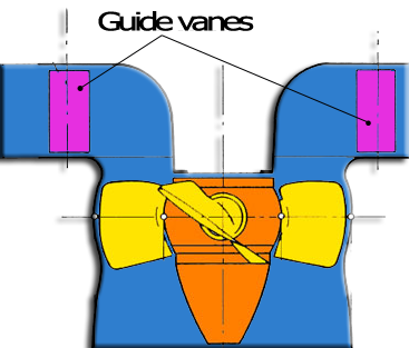
The distributor sets the flow and the rotation of the water before the runner.
Hydroelectric turbines chapter:
- Kaplan turbine power capture 1/3: the components and the operation
- Kaplan turbine power capture 2/3: the distributor-propeller relation
- Kaplan turbine power capture 3/3: the design method
- Hydropower plant tutorial 1/3: site power and runner
- Hydropower plant tutorial 2/3: distributor and volute
- Hydropower plant tutorial 3/3: draft tube, balancing and cavitation
Contents of this page:
- Axial velocity and tangential velocity in the runner
- The head is a pressure: what the runner really absorbs
- The distributor swirl: a share of the head, converted into rotation
- Straightening the stream: the outlet tangential velocity must vanish
- The guide vane angle and the head loss of the distributor
- How Heliciel matches the distributor and the runner
1: Axial velocity and tangential velocity in the runner
Two components must be distinguished in the velocity of the water crossing the runner. The axial velocity, parallel to the axis, is imposed by the flow and the swept section: V = Q / S. The tangential velocity, around the axis, is the rotation the water carries as it reaches the blades: the vortex, or swirl.
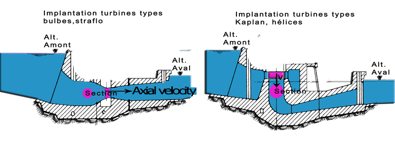
Axial velocity, imposed by the flow; tangential velocity, given by the distributor.
Seen from a rotating blade, these two components combine with the rotational speed to form the apparent velocity, the one that gives the profiles their lift and drag. It is the same reasoning as for any energy-capturing propeller: the lift of the blades, perpendicular to the apparent velocity, produces the torque on the shaft. What changes in a conduit is that the water arrives under pressure and already in rotation.
2: The head is a pressure: what the runner really absorbs
A propeller in a free stream, a tidal or wind turbine, only has the kinetic energy of the stream that reaches it, and the Betz limit bounds what it can take from it. A runner in a conduit is in another situation: the net head, Hn, is offered to it in the form of pressure. As it crosses the blades, the water loses pressure, and this pressure drop, multiplied by the flow, is the power the runner receives. Nothing requires going through a velocity: the axial velocity remains that of the flow, 5.26 m/s on the tutorial example, from the inlet to the outlet of the runner.
This point governs the whole sizing. Converting the head into a velocity by the free jet formula, v = √(2·g·H), would be a mistake: it describes a jet in open air, not a runner under load. The runner must on the contrary "block" the passage, with wide blades and sufficient overlap, so that the pressure drop can build up across it. Heliciel computes this pressure drop by blade element theory in penstock mode, as the axial thrust referred to the section of the annulus.
3: The distributor swirl: a share of the head, converted into rotation
The distributor uses the pressure of the water to force it through its guide vanes, oriented so as to create a vortex. A share of the head thus becomes rotational kinetic energy, the tangential velocity Vθ. In the casing and the distributor, this rotation is that of a free vortex: the product Vθ·r is conserved, it is the circulation constant K, and the tangential velocity increases towards the axis.
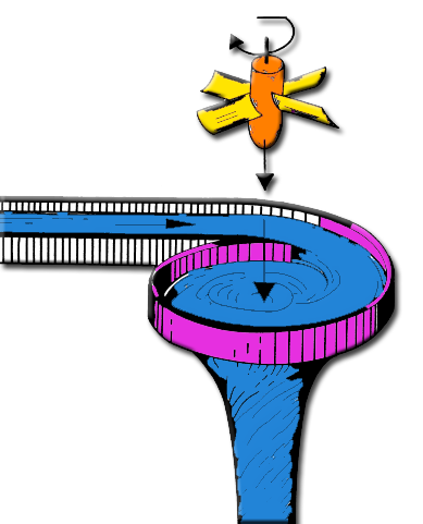
The free vortex of the distributor: Vθ·r constant, hence a faster rotation near the axis.
The distributor creates no energy: what it sets in rotation, it takes from the pressure. At the runner inlet, the static pressure is lower by ½·ρ·Vθ² than it would be without rotation. This swirl head, (⟨Vθ²⟩inlet − ⟨Vθ²⟩outlet)/2g, is a share of the net head, in the same way as the static pressure drop. On the tutorial example it is 0.45 m out of 3.4 m, that is 53 kW on 12 m³/s. The runner absorbs it like the rest.
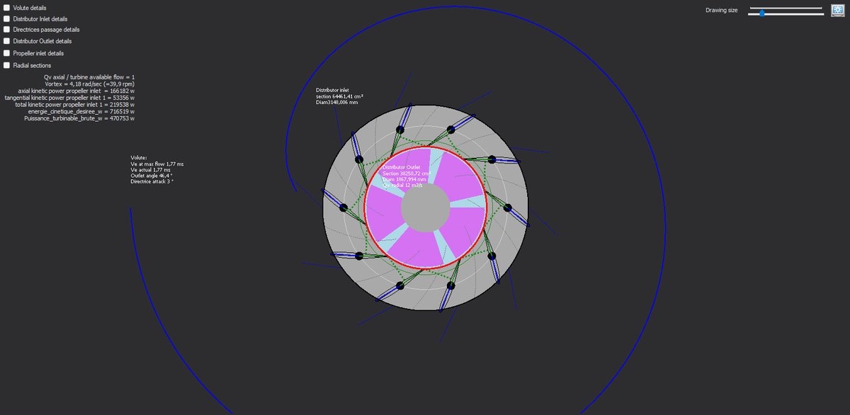
In the top view of Hydro Turbine design, Heliciel displays the swirl produced (4.18 rad/s on the example) and the tangential kinetic power it carries to the runner inlet.
Hydro Turbine interface of Heliciel (requires a Mecaflux Suite license)
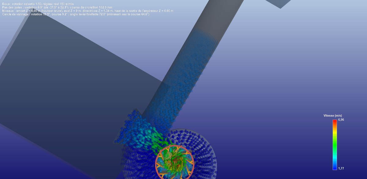
3D top view: the spiral casing carries the trajectories, at constant velocity, all around the distributor.
4: Straightening the stream: the outlet tangential velocity must vanish
Any velocity leaving the runner reveals energy that escapes us. Now a runner that takes torque from a purely axial stream sets the water in rotation by reaction, in the direction opposite to its own rotation: this is the induced tangential velocity, an energy lost in the draft tube.
The reaction to the torque: without a distributor, the water leaves the runner rotating the wrong way.
The distributor gives the answer. If the water enters the runner with a rotation opposite to the one the runner induces, the two cancel out and the water leaves without rotation: the runner has converted all the energy of the inlet vortex into torque. This is the Euler turbomachine equation: the shaft power is ρ·Q·ω·(r₁Vθ₁ − r₂Vθ₂). With Vθ₂ = 0, the angular momentum the distributor must supply follows from the head to be absorbed: K = g·H_runner / ω for a hydraulic efficiency of 1.
The right balance is therefore reached when the tangential velocity produced by the distributor and the tangential velocity induced by the runner cancel out, and when the head absorbed by the runner, plus the head losses of the installation, equals the gross head of the site. A distributor that does too much leaves an outlet swirl, wasted; a distributor that does not do enough lets the reaction of the runner turn the water the wrong way. On the example, Heliciel returns a mean outlet tangential velocity of 0.07 m/s for 2.98 m/s at the inlet: the stream is straightened.
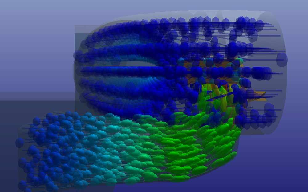
The front cut: the particles swirl in the casing, dive through the runner and slow down in the elbow draft tube.
5: The guide vane angle and the head loss of the distributor
The guide vane angle follows from the two velocities to be produced at the passage. For a Kaplan-type ring distributor, with a volute, the tangent of the vane angle is the ratio of the axial velocity to the tangential velocity: angle = atan(Va / Vt). For a bulb-type annular distributor, without a volute, it is the reverse: angle = atan(Vt / Va). With an axial velocity of 6 m/s and a tangential velocity of 4.4 m/s, this gives 53.7° in the first case and 36.2° in the second.
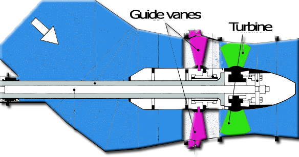
On an annular distributor, the deflection angle of the water is directly the vane angle.
The deflection imposed on the water costs a head loss, all the greater as the angle is large: a small angle costs little, a 90° deflection costs the most. The volute, by giving the stream its tangential path in advance, allows high tangential velocities without high losses in the vanes. Heliciel computes the distributor loss in four terms, after Idel'cik: the angle of attack at the guide vane inlet, the narrowing of the passage between them, the widening at the outlet and the elbow towards the runner. On the example, the ten-vane NACA distributor opened at 51.7° costs 0.055 m.
6: How Heliciel matches the distributor and the runner
In Hydro Turbine design, the Distributor tab carries the number, the profile and the opening of the guide vanes, the height b0 and the pivot circle; Heliciel derives the circulation constant K from them and sends it to the runner as the upstream tangential velocity, ω = K / ⟨r²⟩, the rigid rotation that carries the same angular momentum as the free vortex over the runner annulus. The Propeller Solver opens the guide vanes by the Euler equation, then adjusts the blade overlap until the absorbed head, static plus swirl, and the losses of the water path close on the gross head.
The runner-distributor pair is therefore not sized in two steps but together, and the balance reads in three figures on the Results tab: the net head the path leaves (85% of the gross head on the example), the shaft power referred to the available power (97%), and the overall efficiency before the generator (83%). The distributor design tutorial walks through these settings on the 12 m³/s case.
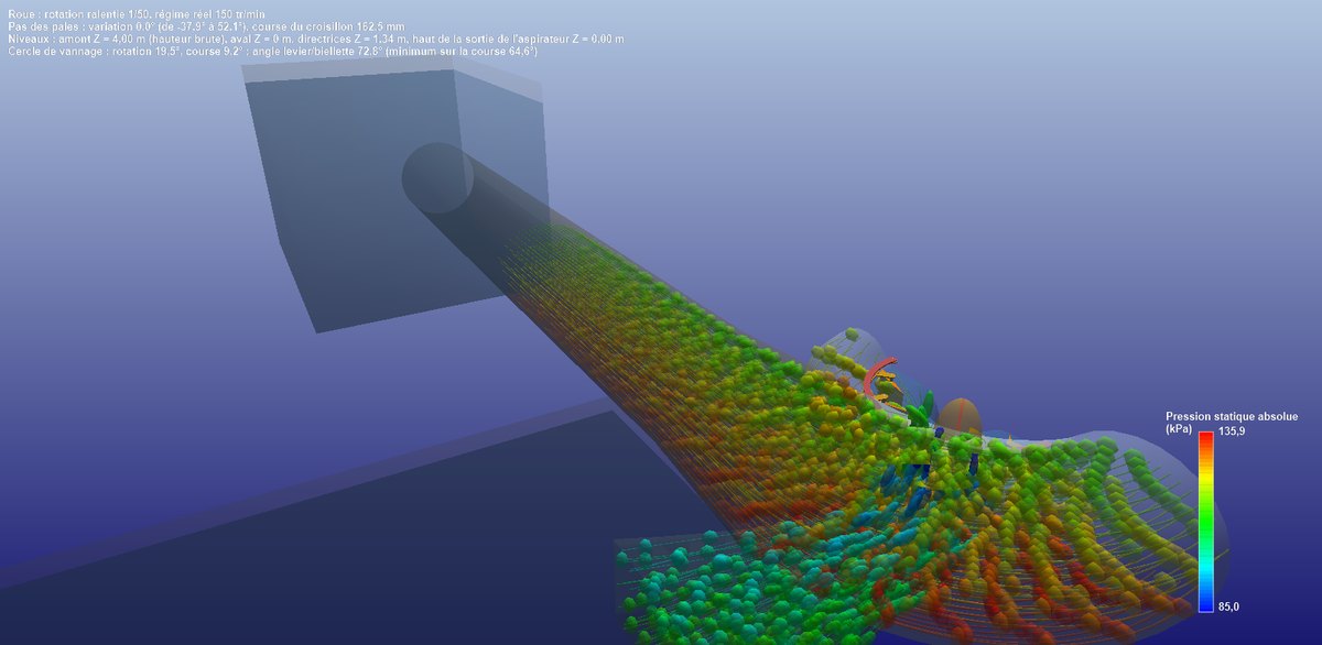
The three-quarter cut, trajectories coloured by pressure: it drops in the casing as velocity rises, falls through the runner, then recovers in the draft tube.
To go further, we can move on to the design method of a Kaplan turbine, or go back to the blade elements of energy-capturing propellers that underlie the computation of the runner.
 Global site map
 Mecaflux
 Tutorials Mecaflux Pro3D
 Tutorials Heliciel
 Tutorials Heliciel PRO CFD
 Mecaflux Store
 Compare software functions
 Quotes, Orders, Payment Methods
 project technical studies