
Hydraulic energy capture by propeller or Kaplan turbine 1/3: components and operation
Harnessing hydraulic energy with a propeller or Kaplan turbine turns the head of a site, a pressure, into torque on a shaft. Four components work together: the spiral casing that brings the water in, the distributor that sets it in rotation and regulates the flow, the runner that takes the energy, the draft tube that recovers what is left. This first part describes these components, the types of turbines, the power of a site and the efficiencies; the next two deal with the relation between distributor and propeller and the design method.
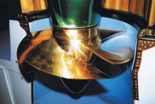
A Kaplan turbine: the water comes in through the casing, rotates in the distributor, crosses the runner and leaves through the draft tube.
Hydroelectric turbines chapter:
- Kaplan turbine power capture 1/3: the components and the operation
- Kaplan turbine power capture 2/3: the distributor-propeller relation
- Kaplan turbine power capture 3/3: the design method
- Hydropower plant tutorial 1/3: site power and runner
- Hydropower plant tutorial 2/3: distributor and volute
- Hydropower plant tutorial 3/3: draft tube, balancing and cavitation
Contents of this page:
- Why an accessible method
- Impulse and reaction turbines: Pelton, Francis, Kaplan
- The hydraulic power of the site: gross head, net head, head losses
- Efficiency of the turbine, the generator and the installation
- The four components: casing, distributor, runner, draft tube
1: Why an accessible method
Harnessing hydraulic energy is an example of inventiveness: the principles tamed over the centuries have given the most modern power plants. In the race for clean energy, a hydraulic turbine remains a way to produce localized energy, sized in harmony with its site. But the profitability of the project requires a reasoned design of each component, and many small sites are neglected because the literature, rich as it is, remains reserved for a mathematical audience. Yet mathematics is only a reflection of physical phenomena: it must be possible to describe them in natural language.
The computations remain unavoidable. We entrust them to Heliciel, which computes the runner by blade element theory (BEM, Blade Element Momentum) and sizes the structure around it in its Hydro Turbine design workshop: casing, distributor, draft tube, head losses and head balance of the water path. We thus stay focused on the physical phenomena and the energy transformations. This article offers a complete method, tools, and an example tutorial to put the design of a small propeller power plant within everyone's reach. It remains open to your contributions (contact@heliciel.com).
The useful mathematical foundations are gathered in a reminder on the relation between power, energy, work and flow, to be consulted alongside.
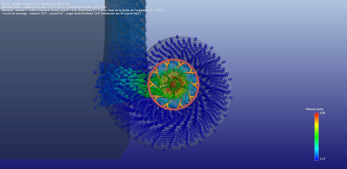
The example installation in 3D perspective: the spiral casing, the distributor, the runner, and the water trajectories coloured by velocity, blue in the spiral, green and yellow at the runner.
Hydro Turbine interface of Heliciel (requires a Mecaflux Suite license)
2: Impulse and reaction turbines: Pelton, Francis, Kaplan
Harnessing the energy of water takes various forms depending on the power of the site. The two determining parameters are the head and the flow, and two families are distinguished.
Impulse turbines work only with the kinetic energy of the fluid, at ambient pressure: the Pelton turbine, made for high heads and low flows, or the Crossflow turbine.
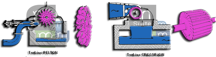
Impulse turbines: a jet, a wheel, atmospheric pressure.
Reaction turbines combine kinetic energy and pressure energy, that is the pressure difference between the inlet and the outlet of a turbine placed in a conduit: the Francis turbine suits medium heads and velocities, the Kaplan or propeller turbine suits low heads and high flows.
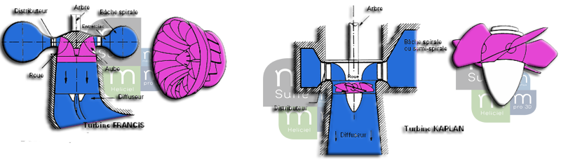
Reaction turbines: Francis and Kaplan work in a conduit, under pressure.
The Heliciel site is dedicated to propellers: we therefore detail the design of bulb, Straflo, Kaplan or propeller turbines, which turn hydraulic power into mechanical power through a propeller. The specific speed tells, for your head and your flow, which of the three families is suitable: Heliciel computes it and locates it on the manufacturers' chart.
3: The hydraulic power of the site: gross head, net head, head losses
The hydraulic power of the site depends on the height difference H, in meters, between the surfaces of the upstream and downstream basins, and on the flow Q, in m³/s, that passes through the installation:
P (W) = Q (m³/s) × H (m) × ρ (kg/m³) × g (m/s²)
with ρ the density of water and g the acceleration of gravity. A 12 m³/s site under 4 m thus carries 12 × 4 × 999.7 × 9.81 = 470,750 W, that is 471 kW gross: this is the tutorial example.
Let us distinguish the gross head from the net head. On its way down from the upstream basin to the downstream basin, the water rubs against the walls and meets obstacles that take energy from it. This loss of energy in the conduits is called the head loss and is expressed in meters: everything happens as if the head were lower.
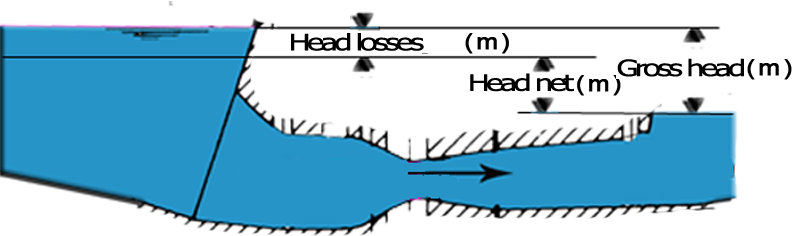
Gross head, head losses, net head.
- Gross head Hb (m): the level difference between the upstream basin and the downstream basin.
- Net head Hn (m): Hb minus the head losses of the path. Heliciel computes them item by item in Hydro Turbine design: penstock (Colebrook formula), casing, distributor, junction tube, elbow and draft tube.
We therefore speak of gross power or net power depending on the head put into the formula. The net power, ρ·g·Q·Hn, is the one the runner can receive: Heliciel calls it the available power.
The axial velocity of the water in the runner is derived from the flow and the swept section: V (m/s) = Q (m³/s) / S (m²), S being the annulus between the hub and the blade tips.
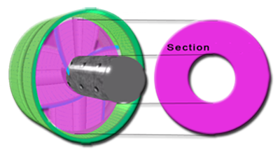
The section swept by the propeller: an annulus between the hub and the blade tips.
As it crosses the runner, the water gives up energy to it: its pressure falls from inlet to outlet, and this pressure drop, for a given flow, is what the runner absorbs. The net head must therefore be enough for the head the runner consumes, draft tube included: this is the equilibrium balance we will see in the method.
4: Efficiency of the turbine, the generator and the installation
To obtain electricity, we turn hydraulic power into mechanical power on the shaft, then into electrical power in a generator. None of these components is perfect.
- Turbine efficiency = mechanical power (W) / hydraulic power (W). Heliciel distinguishes the path efficiency, Hn/Hb, the runner efficiency, shaft power over available power, and the overall efficiency, shaft power over gross power of the site.
- Generator efficiency = electrical power delivered (W) / mechanical power (W).
- Overall efficiency = electrical power delivered (W) / hydraulic power of the site (W).
On the tutorial example, Heliciel returns 390 kW at the shaft for 402 kW available and 471 kW gross: 85% for the path, 97% for the runner, 83% in total before the generator. These values are those of the model at the design point, to be compared with an engineering study of the structure.
5: The four components: casing, distributor, runner, draft tube
The runner, or turbine propeller, is the rotating part that converts the energy of the water into mechanical energy. In a conduit, it works under pressure: its wide blades must "block" the passage so that the pressure drop can build up across it. Heliciel computes it by blade element theory in penstock mode, where the stream tube is imposed by the shroud and the blade tip losses are neutralized by the small clearance.
The distributor is a ring of profiled, adjustable vanes, the guide vanes, which direct the water and control its rotation, the tangential component of its velocity, according to their opening. It also serves as the flow regulating valve. On bulb turbines, the ring of guide vanes alone provides the rotation; on Kaplan turbines, the distributor is placed at the center of a volute that has already given the stream its tangential path, and the guide vanes complete its work. The deflection imposed by the vanes costs a head loss: it must stay minimal, and a strong deflection calls for a volute.
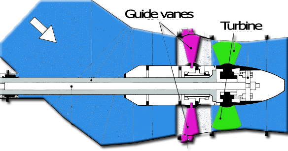
A bulb turbine distributor: the ring of guide vanes alone sets the water in rotation.
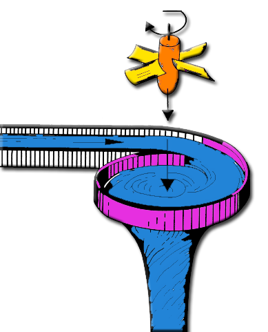
The vortex the distributor gives the water before the runner.
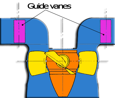
On a Kaplan, the volute and the distributor share the task of setting the water in rotation.
The spiral casing wraps around the distributor and distributes the flow all around it, keeping the water velocity constant from one section to the next. Heliciel draws it in eight sections and computes its allowable velocity according to its material.
The draft tube, or diffuser, is a divergent cone placed behind the runner. It slows the water down to the downstream basin and thus turns the residual velocity into a depression at the runner outlet: the runner sees a head larger than its mere height above the downstream level. This recovery system is detailed in the third part of the tutorial, devoted to the draft tube.
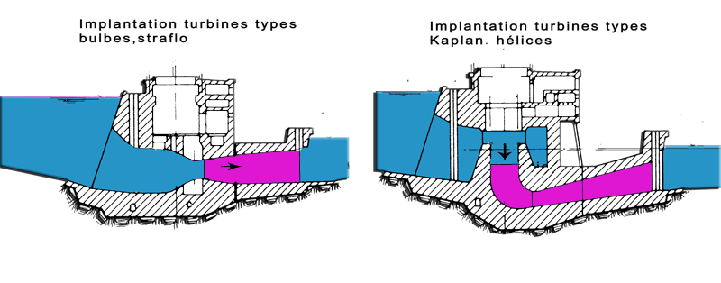
The draft tube: a cone that slows the water down and lowers the pressure behind the runner.
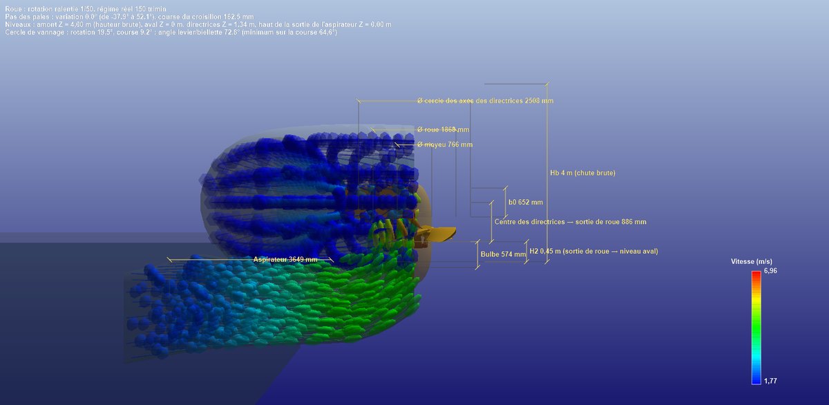
The dimensioned front cut: the particles swirl in the casing, dive through the runner and slow down in the elbow draft tube, below tailwater level; the runner, bulb, H2 and gross head dimensions are shown.
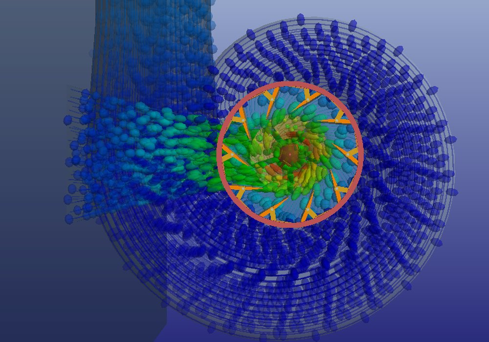
Close-up of the distributor: the gate ring, the guide vanes and the water particles, blue in the casing, green and yellow as they accelerate towards the runner.
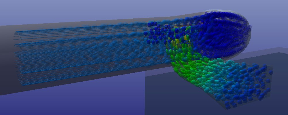
The elbow draft tube with its rectangular outlet, seen from downstream: the trajectories slow down and spread out to the river.
After this presentation of the components, let us see how to size them and evaluate the performance of the site: the relation between the distributor and the propeller. To go further, we can also open directly the user guide of Hydro Turbine design.
 Global site map
 Mecaflux
 Tutorials Mecaflux Pro3D
 Tutorials Heliciel
 Tutorials Heliciel PRO CFD
 Mecaflux Store
 Compare software functions
 Quotes, Orders, Payment Methods
 project technical studies