
hydropower turbine propeller:
- Part 1: Parameters and operating parts of a turbine system.
- Part 2: The relation stator guide vanes and propeller
- Part 3: The design method of hydraulic turbine
- Part 4: Tutorial designing a turbine system.
- Tutorial hydroelectric turbine design 1/3 :Site power and turbine design
- Tutorial hydroelectric turbine design 2/3 :Design :guide vanes or stator
- Tutorial hydroelectric turbine design 3/3 :Choice sections, design draft tube
Tutorial hydroelectric turbine design 2/3 : Design guide vanes or stator:
axial guide vanes:
- Effects of the tangential speed upstream
- Angle of the fins of the distributor and flow diversion
- guide vanes design and evaluation of pressure drop
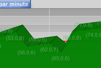
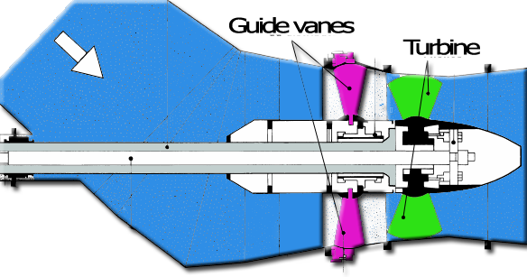
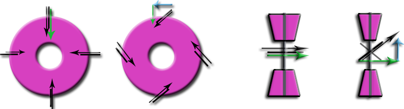
stator or guide vanes upstream of the turbine produces a tangential velocity (vortex), of direction opposite to the tangential velocity induced by the turbine.. The tangential velocity induced by the turbine will be recovered. Increased velocity through the turbine can be achieved without changing the flow rate so as to utilize the energy of high load, by converting it into tangential speed. Adjusting the angle of the vanes of the distributor will adjust the tangential velocity..Let us take our turbine designed in turbine design Tutorial 1/3 ,updated to operating point and design speed of 53.2 rpm. In the results of HELICIEL software, select the tab "fluid velocities". On the graph downstream tangential speeds, let your cursor at the element producing the most tangential velocity (element4), to show the tooltip with the value in radians / second:
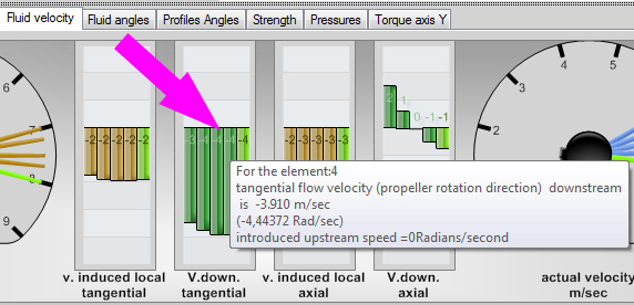
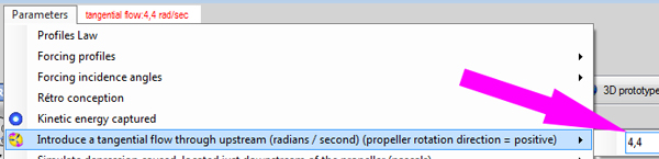
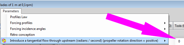
In our example, the induced tangential velocity downstream of the turbine is around 4.4 rad/sec at the element level 4.So we need to introduce a tangential velocity of 4.4 rad / sec with our stator guide vanes.For this, use the parameter menu / introduce a tangential velocity, and enter 4.4 rad / sec:
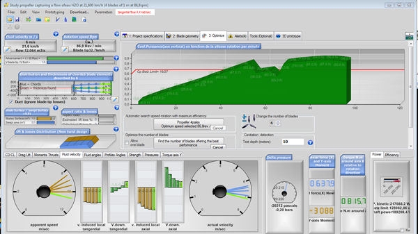
- Area calculations without converging: Certain conditions of speed and impact, generate negative axial velocities in some elements, which would result in a return of fluid back and turbulence, degrading conditions of flow around profiles. Heliciel considered these areas results too uncertain,null , in terms of performance for elements disturbed. In the graph, this results in a discontinuity in performance depending on the rotational speed:
- The Betz limit seems exceeded!
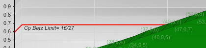
- but this is an illusion due to the fact that it is based only on the axial flow, without integrating the contribution of the tangential flow. The tangential flow introduced upstream
 gives us additional power, we could increase the power by increasing the tangential flow, but this will result in an increase in the pressure drop in the distributor / stator which should increase the angle of deflection of the stream.
 - We can also estimate the tangential velocity downstream of the turbine, the average tangential velocities should be as close as possible to zero,to represent an adjustment of the flow and cancellation downstream losses..
 if the tangential speed, introduced into the propeller is greater than the tangential velocity produced by the propeller, the flow will have a non-zero tangential velocity downstream. Which is a lost energy.
Angle of the baldes of the distributor and flow diversion:
We can estimate the angle of the vanes of the stator guide vanes, using the axial velocity and the tangential velocity to produce.
- tangential velocity: The tangential velocity(m/sec) to produce is calculated using the velocity in radian second:
- tangential velocity (m/sec) = angular velocity (rad/sec) x radius tip blade(m) So for our example:
- tangential velocity(m/sec) = 4.4(rad/sec) x 1(m) = 4.4m/sec
guide vanes kaplan:
|
guide vanes bulb:
|
- axial velocity =(Qv / section) =(12 /2.01)= 5.97 m/sec
- Angle of the vanes:
- For a guide vanes in crown Kaplan (with volute):
- tangent (Angle ailettes) = axial velocity /tangential velocity
- =>blades angle = Atan(axial velocity / tangential velocity )
- =>blades angle = Atan( 5.97 / 3) = 63 °
- For a guide vanes ring bulb type:
- tangent (blades angle) = tangential velocity /axial velocity
- =>blades angle = Atan(tangential velocity /axial velocity )
- =>blades angle = Atan( 3 / 5.97 ) = 26 °
- For a guide vanes in crown Kaplan (with volute):
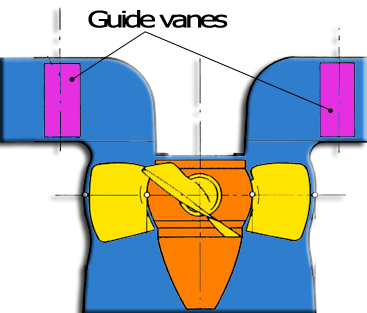
Guide vanes design and evaluation of pressure loss:
The losses in the guide vanes are related to the angle of deflection experienced by the fluid. For vanes guides rings, bulbs types,the angle of deflection is directly that of the blade. In the Kaplan-type systems, the volute gives to fluid a tangential trajectory. The angle of deflection of the fluid will, also equal to the angle of the blades. A low angle of blades produces minimal pressure loss. Volute allows to generate significant tangential velocities without inducing high losses by diverting the fluid in the grid blades.Note that a stator bulb type will have a low deflection angle if the axial speed is greater than the tangential speed. A guide vanes Kaplan type, due to the volute has a low angle of deflection for high tangential velocity. This predisposes the guide vanes with volute, to power plants, whose load height (transformed into tangential velocity) is high and systems bulbs for high throughput, and low drop.The volute will be sized to maintain a constant speed around the guide vanes. His section will therefore decline to consider the volume of fluid drained into the upstream portions:
- Design of a ring-type guide vanes or a stator:
A ring-type guide vanes is a propeller does not rotate (stator).We will use Heliciel to calculate the delta pressure between the upstream and downstream of a propeller with a speed of almost zero rotation, and a number of blade, corresponding to the number of blades in our guide vanes. The propeller should generate a tangential velocity downstream of about 4.4 rad / sec. We can even, if we wish, export the 3D igs file stator blades, to a CAD to realize them.
After having successfully saved our turbine (File menu / Register), we will transform it into stator ring type:
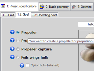
- CAUTION! : 1.2Objectif tab, check propeller propulsive
- Tab 3. optimize / number of blade:
change number of blades from 4 to 12

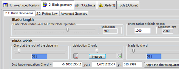
- Geometry is enhanced by decreasing the widths of cords foot and the blade tip, so as to minimize friction and pressure losses.We set the chord at blade root to 311 mm and the same to the tip chord (remember to the linearized distribution chord).We will keep the tip radius, and blade root 1000 and 600 mm.
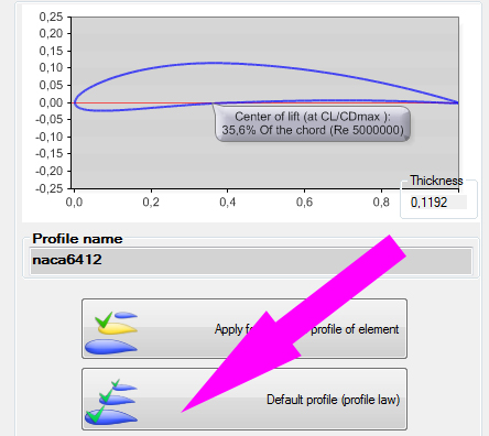
- We will select a different profile, more curved, generating more lift for our stator,the naca 6412.To do this, use the database and apply the naca 6412 profile as the default:
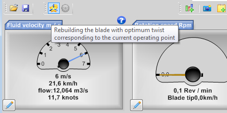
- We keep the speed of 6 m / sec and as we have not touched the foot radius and blade tip,The throughput section is the same as the turbine, and the flow rate is always 12 m3/sec.
- Combined with a rotational speed (tab 1.3 operating point) set to 0.1 rpm to simulate a zero rotational (a zero rotational velocity causes errors in the equations)
- In the parameters menu, we remove the tangential flow by setting it to 0
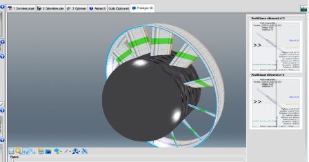
Here the parameters of our stator are input, it remains to start rebuilding : Our 3D model of stator ring is created :
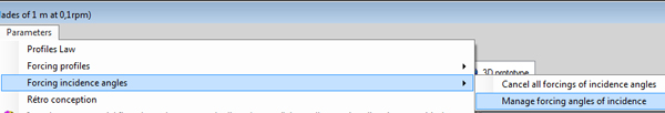
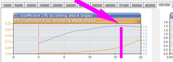 and deduce that the angle of attack, generating most Cz (lift) thus the more tangential force , is 16 degrees to the naca 6412 at Re 1 million. So we force angle of attack to 16 degrees using the "parameter menu / manage forcin angle incidences:
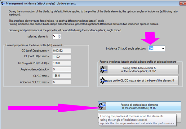
and apply the incidence of 16 degrees at all profiles:
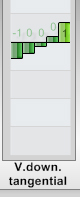
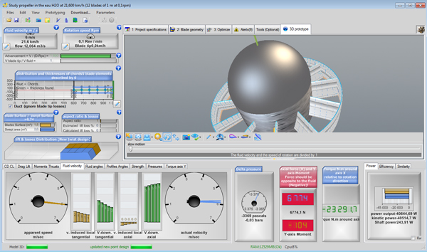
- The tangential speed at the outlet of stator
- and the pressure loss when the fluid passes through the stator:
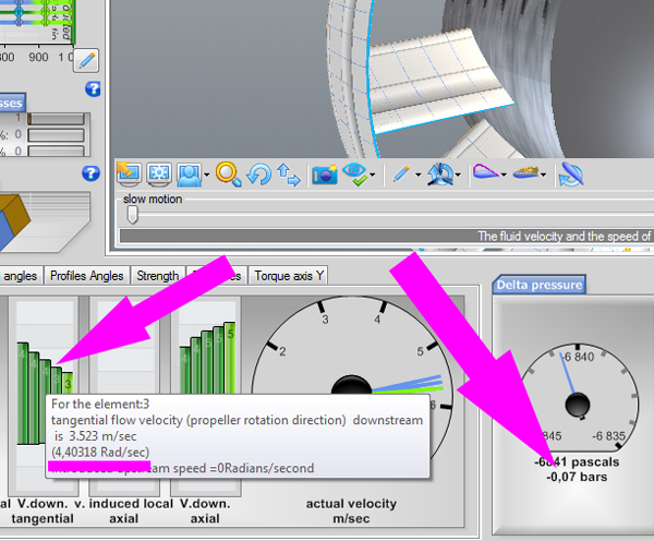 The tangential velocity produced is about 4 rad/sec and the pressure loss is 0.07 bars about 0.7 meters. We finished the calculation of our stator guide vanes ring type,,
Summary: We have seen how the sator or guide vanes, allows us to transform a portion of the load height into kinetic energy by rotating the flow upstream of the propeller .This rotation generates an increase in speed through the blades and blade angles of attack more favorable to transform torque force. A tangential velocity upstream properly adjusted must balance the tangential velocity produced by the turbine. This balance is verified by the absence of rotation of the flow downstream of the propeller. The designer of the stator, or guide vanes, will find a compromise between pressure loss caused by the deflection angle, and the axial and tangential velocity ratio to produce. The choice of the passage section of the distributor allows the designer to control the ratio between the axial velocity and the tangential velocity, Thus the deviation angle to create, for a maximum rotation of the upstream flow..
Another factor increasing the power of the propeller: the diffuser or vacuum draft tube.next:Tutorial hydroelectric turbine design 3/3 :Choice sections, design draft tube
hydropower turbine propeller:
- Part 1: Parameters and operating parts of a turbine system.
- Part 2: The relation stator guide vanes and propeller
- Part 3: The design method of hydraulic turbine
- Part 4: Tutorial designing a turbine system.
- Tutorial hydroelectric turbine design 1/3 :Site power and turbine design
- Tutorial hydroelectric turbine design 2/3 :Design :guide vanes or stator
- Tutorial hydroelectric turbine design 3/3 :Choice sections, design draft tube
 Global site map
 Mecaflux
 Tutorials Mecaflux Pro3D
 Tutorials Heliciel
 Mecaflux Store
 Quotes, Orders, Payment Methods
 project technical studies