
Boat Propeller 2/5: Operating Parameters and Blade Geometry
Part 1 · Part 2 · Part 3 · Part 4 · Part 5
To design a boat propeller in Heliciel, we first enter the operating parameters (fluid, goal, profile, number of blades, speed), then we define the blade geometry: length, root radius, chords. In part 1, we wrote the design brief. Now let us see how to meet it, starting from a water propulsion propeller model.
On this page:
- Opening the boat propeller model and checking its parameters
- Choosing the number of blades and the boat speed
- Setting the diameter and the blade length
- Setting the hub, the chords and the blade shape
- Building the propeller and looking at the 3D model
1: Opening a boat propeller model and checking its parameters
We open a water propulsion propeller model (boat) in Heliciel, as at the end of part 1.
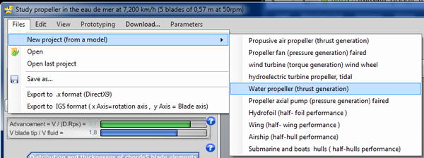
Files > New project (from a model): choosing the water propeller.
This default project already sets three parameters, which we check one by one. First, the fluid parameters are those of sea water.
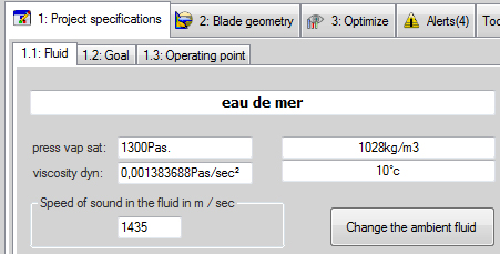
Tab 1.1: Fluid. Heliciel shows sea water, here at 10 °C, with a density of 1,028 kg/m³.
Next, the project goal is set to propulsion propeller.
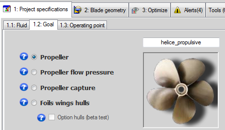
Tab 1.2: Goal. The "Propeller" choice is ticked.
Finally, the profile law is set to a constant profile, the NACA 1408: every element of the blade receives this same profile.
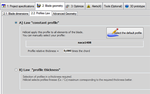
Tab 2.2: Profiles Law. The "constant profile" law applies the naca1408 (relative thickness 0.080) to the whole blade.
2: Choosing the number of blades and the boat speed
The default water propulsion propeller project has 5 blades. We want a propeller that is simple to build, so we change the number of blades right away in the 3: Optimize tab and bring it down to 2.
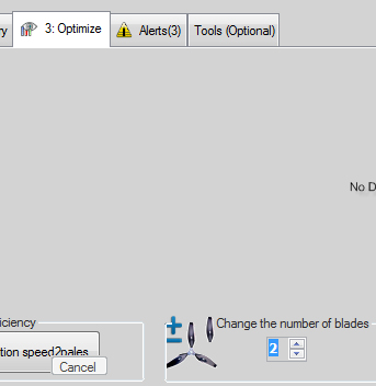
Tab 3: Optimize. The "Change the number of blades" setting is brought down to 2.
We then set the operating point, notably the cruising speed, in the 1.3: Operating point tab. We enter 1.55 m/s for the fluid velocity upstream of the blade, that is 3 knots (Heliciel displays 3.013 knots, or 5.580 km/h).
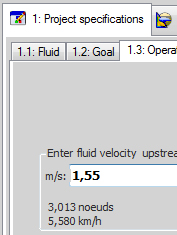
Tab 1.3: Operating point. The fluid velocity upstream is 1.55 m/s, converted by Heliciel into km/h and knots.
We set the rotational speed aside for now, because we do not know it yet. After defining the geometry, we will use the function that searches for the optimum rotational speed (part 3).
3: Setting the propeller diameter and the blade length
Let us move on to the blade geometry. We start with the diameter. We saw that lift losses at the blade tip (see losses at the tip of a wing or blade) can lower the efficiency if the blade is short and the lift is spread too close to the tip. We therefore look for the longest possible blade, wide at the root and narrow at the tip.
The maximum blade length is found by taking into account the minimum navigable depth (the propeller must not scrape the bottom) and the position of the propeller shaft: the distance between the hull and the shaft also sets the maximum radius.
After many discussions among:
- the hull designer;
- the user of the boat;
- the mechanic who will fit the motor;
- Pythagoras, who tells us that the angle between the propeller shaft and the surface must stay as small as possible so that the force is well oriented;
- the neighbour who happens to pass by;
- the neighbour's brother-in-law and his youngest, who wants to climb into the boat while it is still full of resin;
- the lady passenger, who says she would rather not get her knees wet when stepping down,
we decide, to satisfy everyone, that the blade may have a maximum length of 200 mm, that is a propeller diameter of 400 mm. We therefore set this length to 200 mm in the 2: Blade geometry tab, section 2.1. Heliciel asks there for the radius at the blade tip, that is the distance between the axis of rotation and the blade tip, or half the diameter.
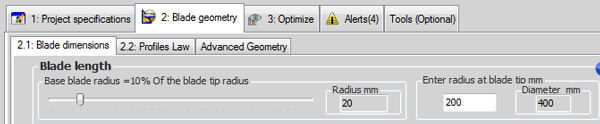
Tab 2.1: Blade dimensions. The radius at the blade tip is 200 mm, which gives a diameter of 400 mm.
4: Setting the blade root radius, the chords and the blade shape
The blade root is set with a slider, as a percentage of the blade length. The radius at the blade root sets the hub diameter. We choose a 40 mm hub to house a blade fixing system: the root radius is therefore 20 mm, or 10% of the blade length. The part of the blade near the axis provides little thrust, because its speed is low compared with the blade tip. We avoid going below 10% of the blade length.
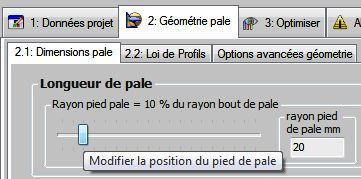
The slider for the blade root position: 10% of the blade tip radius, a root radius of 20 mm (screenshot of the French interface).
We set the blade width at the root (chord of the root profile) to 100 mm, and the width at the blade tip (chord of the tip profile) to 20 mm.
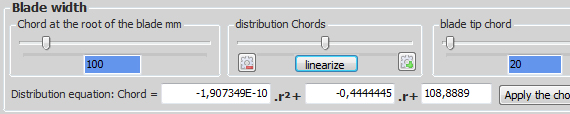
The "Blade width" group: chord of 100 mm at the root, 20 mm at the tip, and the "linearize" button in the middle.
For the distribution of the intermediate chords, we click linearize: Heliciel then spreads the chords linearly between the blade root and the blade tip.
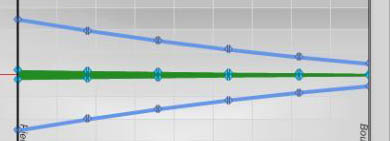
The chart of chords (blue) and thicknesses (green): the chord decreases in a straight line from the blade root to the tip.
5: Building the boat propeller and looking at the 3D model
Our geometry, a provisional draft, is set. We start the construction and test the performance of our model with the Rebuild propeller function, in the toolbar at the top left of the software:  . Each time we change the geometry, the Rebuild button lights up to tell us that the propeller must be rebuilt if we want to update the results and the 3D model.
We get our propeller:
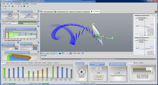
The two-blade draft propeller in the Heliciel 3D prototype, with the coefficient histograms, the thrust and torque gauges and the powers.
The rotation control button, in the toolbar below the 3D model, stops the propeller's rotation so that we can look at it.
To go further, we can now choose the rotational speed according to the performance we want, in part 3 of the tutorial.
 Global site map
 Mecaflux
 Tutorials Mecaflux Pro3D
 Tutorials Heliciel
 Tutorials Heliciel PRO CFD
 Mecaflux Store
 Compare software functions
 Quotes, Orders, Payment Methods
 project technical studies