
Energy harvesting propeller: wind turbine, tidal turbine and hydroelectric turbine
An energy harvesting propeller turns the kinetic energy of a fluid stream into power on its shaft: the fluid passing through it carries a power P = 0.5 × density × speed³ × disc area, and the Betz limit lets us capture only 16/27 of it, about 59%. This is the principle of the wind turbine, the tidal turbine, the windmill and the hydroelectric turbine. Air or water changes some constraints, but the energy conversion stays the same. Here we look at the available energy, the energy we can capture, and the blade length that follows.
| The energy available | The energy that we can capture | wind turbines | tidal turbines | hydroelectric turbines |
Capturing the energy of fluid streams with a propeller is found in many systems that produce energy and driving force.
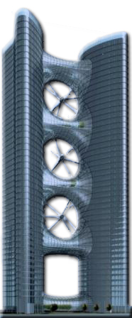
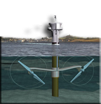
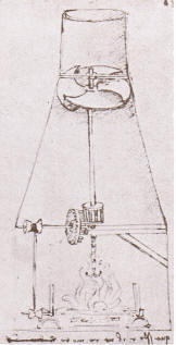
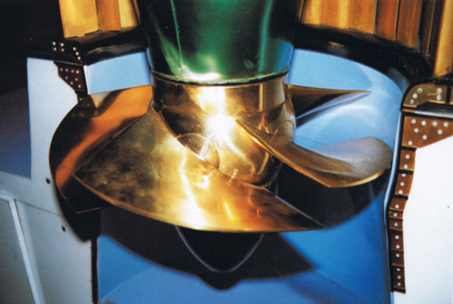
From left to right: wind turbines integrated into a building (project), a tidal turbine, a Leonardo da Vinci drawing where the hot air of a hood drives a propeller, and the runner of a hydroelectric turbine. Four eras, four fluids, one principle.
Before studying these machines in detail, we take stock of this method of energy conversion.
1: Available energy: the power of a stream of wind or water
Before getting into the design of the propeller, we must assess the energy need and compare it with the energy available at the installation site. To choose the design wind speed, we can also consult Heliciel's wind map.
The energy drawn from the fluid is kinetic energy, that is, the energy of an object's speed:
- equation 1: E (joule) = 0.5 × mass of the object (kg) × speed² (m/s).
Power is the amount of energy per second. In one second, the mass of fluid passing through the propeller equals the volume of fluid crossing the propeller disc, multiplied by the density:
- equation 2: mass (kg) = density (kg/m³) × propeller disc area (m²) × speed (m/s).
The power of the fluid passing through a propeller is therefore calculated as:
- equation 3: P (W) = 0.5 × density (kg/m³) × speed³ (m/s) × disc area (m²).
This equation shows the factors behind the power of our energy harvesting propeller, and their relative weight. Power is a cubic function of speed: doubling the speed multiplies the power by eight. After speed, the area of the disc swept by the propeller is the best indicator of its potential.
A hypothetical example to fix ideas: in air of density 1.25 kg/m³, at 8 m/s, a 10 m² disc has 0.5 × 1.25 × 8³ × 10 = 3,200 W passing through it. In water at 2 m/s, the same disc has 0.5 × 1,000 × 2³ × 10 = 40,000 W passing through it: water four times slower than the wind still carries twelve and a half times more power, because it is about 800 times denser.
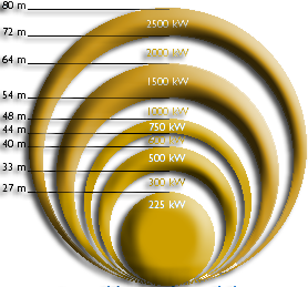
Wind turbine power versus propeller diameter, from 225 kW at 27 m to 2,500 kW at 80 m: the larger the swept disc, the higher the power.
2: Capturable energy: the Betz limit and the power coefficient
Every energy transformation involves losses. The first, unavoidable loss comes from this: to extract all the power from the fluid speed, we would have to take away all its speed as it crosses the propeller. But if we stop the fluid entering the propeller dead, where do we put it? It has to be evacuated on the other side of the propeller, and fast enough to leave room for the fluid arriving. So we can only use a part of the power of the stream. The more speed the propeller removes from the fluid, the more it blocks the passage, and the more the fluid loses its energy without passing it to our propeller.
For a more mathematical explanation, we can read the Froude theory, which relies on the concept of momentum.
Between the case where no speed is removed from the fluid and the case where the passage is blocked, there is a case where the maximum possible energy is extracted. This ideal case corresponds to a reduction of one third of the fluid speed, relative to its upstream speed, at the disc (the fluid has lost two thirds of its speed far behind the propeller). The maximum recoverable energy, calculated and demonstrated by Betz, is 16/27 of the energy of the fluid: this is the Betz limit.
- equation 4: Pmax (W) = 16/27 × 0.5 × density (kg/m³) × speed³ (m/s) × propeller disc area (m²).
For air of density 1.25 kg/m³, this gives:
- equation 5A: Pmax (W) = 0.37 × disc area (m²) × wind speed (m/s)³.
For water of density 1,000 kg/m³, this gives:
- equation 5B: Pmax (W) = 296 × disc area (m²) × water speed (m/s)³.
The efficiency of an energy transformation is the ratio of the power obtained after the transformation to the power available before it. Our propeller turns the power of the fluid into power on its shaft. The quality of the propeller shows in its power coefficient (Cp), calculated as follows:
- equation 6: Cp = propeller shaft power (W) / (0.5 × density (kg/m³) × fluid speed (m/s)³ × disc area (m²)).
The theoretical maximum Cp announced by Betz, 16/27 (about 0.59), ignores the losses due to profile drag and the losses at the blade tip. In reality, these losses mean that the best propellers do not exceed 70 to 80% of the Betz limit. This brings the maximum Cp we can hope for down to 0.4 or 0.5.
3: Calculating the blade length of a wind turbine or tidal turbine
If we know the wind (or current) speed and estimate the efficiency Cp, we quickly find the disc area, hence the blade length to give the propeller to deliver the desired power:
- equation 7: disc area (m²) = propeller shaft power (W) / (Cp × 0.5 × density (kg/m³) × fluid speed (m/s)³).
The disc is a circle, of area π × blade length² (π is about 3.14), counting the blade length from the axis, hub included:
- equation 8: blade length (m) = square root of [ (required shaft power (W) / (Cp × 0.5 × density (kg/m³) × fluid speed (m/s)³)) / 3.14 ].
Starting from an optimistic Cp of 0.4, the product Cp × 0.5 equals 0.2:
- equation 8 with Cp = 0.4: blade length (m) = square root of [ (required shaft power (W) / (0.2 × density (kg/m³) × fluid speed (m/s)³)) / 3.14 ].
Two hypothetical examples, with Cp = 0.4 and a shaft power of 1,000 W: in air at 8 m/s (1.25 kg/m³), the blade length is about 1.58 m; in water at 2 m/s (1,000 kg/m³), about 0.45 m. The electrical power available will be lower, because the losses of the generator and of the transmission must still be deducted.
Whether for a wind turbine or a tidal turbine, we now know how to evaluate the blade length from the energy sought and the energy of the fluid. What remains is to combine the rotational speed and the fluid speed: this is the operating point of our propeller.
4: Can a duct beat the Betz limit?
A short interlude: is it possible to exceed the Betz limit? By preventing the flow from bypassing the propeller with a duct around it, some devices seem to exceed it, with figures to back it up. But this trick merely moves the bypass, hence the Betz limit, to the start of the duct.
The propeller's efficiency is Cp = shaft power (W) / (0.5 × density (kg/m³) × fluid speed (m/s)³ × disc area (m²)). If someone tells you their system's efficiency is above 0.59, check that the disc area corresponds to the area actually captured, and not to the area swept by the propeller placed at the end of the inlet cone.
Another trick is to suck out the plug formed behind the propeller, using profiled rings that draw on energy from outside the fluid stream to create a depression behind the propeller. The area really captured is modified here too. The best propellers do not exceed 70 to 80% of the Betz limit.
These ducted systems nevertheless have their advantage: they reduce tip losses and increase the propeller's efficiency, but never above the Betz limit. The gain a duct brings must be weighed against its extra manufacturing cost. Often, with the added material, we could increase the propeller diameter, hence the overall power of the system.
To go further, we can draw the blade plan of a wind turbine and check the site wind speed with the page on wind turbine power versus wind speed. We can also link this energy balance to the wind turbine generator that will absorb the shaft power.
 Global site map
 Mecaflux
 Tutorials Mecaflux Pro3D
 Tutorials Heliciel
 Tutorials Heliciel PRO CFD
 Mecaflux Store
 Compare software functions
 Quotes, Orders, Payment Methods
 project technical studies