
Wing and blade aspect ratio: formula and effects
The aspect ratio of a wing or blade is calculated with the formula AR = b² / S: the square of the span divided by the area. The higher it is, the less energy the wing loses at its tips, and the better its lift-to-drag ratio. For a rectangular wing of constant chord, it reduces to the span divided by the chord. It is a dimensionless number, and it applies equally to a wing, a sail or a propeller blade.
On this page:
- Definition of aspect ratio
- Airfoil performance: an infinite aspect ratio
- The effect of a finite aspect ratio
- Aspect ratio, shape and vortices
1 : Wing aspect ratio formula and typical values
Among the geometric parameters of a wing, the aspect ratio is one of the most important. We define it as the ratio of the square of the span b to the area S of the wing's projection:
AR = b² / S
with b the span (m) and S the wing area (m²). The aspect ratio is a ratio: it has no unit.
For a rectangular wing, whose chord c is constant along the span, S = b·c and the aspect ratio becomes AR = b / c. Hypothetical example: a wing 10 m in span and 1 m in chord has an area of 10 m² and an aspect ratio of 100 / 10 = 10.
Common values go with flight speed: 20 to 40 for gliders and ultralights, 6 to 10 for small and medium-speed aircraft, 2 to 3 for supersonic aircraft. The aspect ratio decreases as the aircraft's speed increases.
2 : 2D airfoil performance: the infinite aspect ratio
The airfoils whose performance is given as Cd and Cl coefficients (Cx and Cz in French) are said to have an infinite aspect ratio: their performance is given without wing-tip losses. When the wind-tunnel tests from which these coefficients are extracted are carried out, the ends of the test wing sit between two plates that cancel the tip losses.
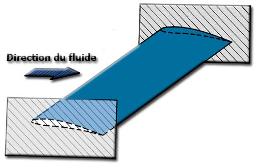
A test wing between two plates: no fluid flows around the ends, as on an infinite wing.
Some aircraft have even been fitted with measuring rigs for airfoils, where plates frame the profile to simulate a wing of infinite length.
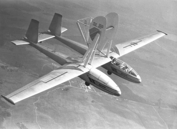
An aircraft fitted with an airfoil test rig above the wing.
The performance of an airfoil is therefore given for an infinite-span wing, hence an infinite aspect ratio. We also call it 2D performance, to tell it apart from 3D performance, which accounts for the finite nature of the real wing or blade.
3 : Effect of aspect ratio on lift-to-drag ratio (Eiffel polars)
The Eiffel curve below shows the impact of aspect ratio on a wing, a sail or a blade of finite length. It gives the 3D lift (Cl) and drag (Cd) coefficients for curved plates of different aspect ratios.
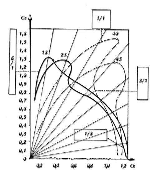
Eiffel polars: the higher the aspect ratio (6/1 against 1/3), the steeper the curve, meaning the lift is obtained at lower drag.
The quality of a wing is its lift-to-drag ratio. The 6/1 plate gives the best ratio: the plate with the highest aspect ratio offers the best efficiency.
The same trend appears on a polar for sails, plotted for four aspect ratios (AR = 6, 3, 1 and 1/3).
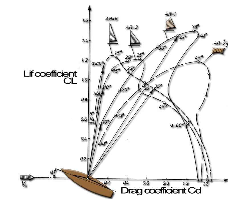
Sail polar for four aspect ratios: the most elongated sail (AR = 6) climbs the straightest, with the least drag per unit of lift.
Let us remember it when building a wing, a sail or a propeller blade: a high aspect ratio means saving energy.
4 : Aspect ratio, wing shape and tip vortices
The tip-loss calculation predicts the 3D performance of a wing from the 2D performance of its airfoils. It accounts for the aspect ratio and for the distribution of vortices, which form mainly at the blade tip but whose influence covers a large part of the wing.
The four wings below, shown schematically in Heliciel, compare two aspect ratios for two wing shapes.
Heliciel video, episode 14: designing and shaping a hydrofoil (8 min 21). Lengthening the foil from 1 m to 1.3 m raises its lift-to-drag ratio from 28.5 to 30.3; chords, profile and generatrix complete the study. Episode page |
Rectangular wing, 9 metres long. Aspect ratio = 18. Lift-to-drag ratio = 32 |
| Tapered wing, 2 metres long. Aspect ratio = 5. Lift-to-drag ratio = 19. | Tapered wing, 9 metres long. Aspect ratio = 33. Lift-to-drag ratio = 36 |
The lift-to-drag ratio rises from 16 to 32 for the rectangular wing as the aspect ratio goes from 4 to 18, and from 19 to 36 for the tapered wing as it goes from 5 to 33.
To go further, we can study the finite-span wing theory, based on the distribution of vortices, or review the basics of wings, hydrofoils and sails.
 Global site map
 Mecaflux
 Tutorials Mecaflux Pro3D
 Tutorials Heliciel
 Tutorials Heliciel PRO CFD
 Mecaflux Store
 Compare software functions
 Quotes, Orders, Payment Methods
 project technical studies