
hydropower by propeller or Kaplan turbine 3/3: Design method
hydropower turbine propeller:
- Part 1: Parameters and operating parts of a turbine system.
- Part 2: The relation stator guide vanes and propeller
- Part 3: The design method of hydraulic turbine
- Part 4: Tutorial designing a turbine system.
- Tutorial hydroelectric turbine design 1/3 :Site power and turbine design
- Tutorial hydroelectric turbine design 2/3 :Design :guide vanes or stator
- Tutorial hydroelectric turbine design 3/3 :Choice sections, design draft tube
Part 3: The design method of hydraulic turbine :
1: basic rules
The method of calculation and design proposed here, allows you to design the elements of a small hydroelectric power plant. The blade design and calculation of pressure losses using two software tools, Mecaflux for head losses,Heliciel and for the design of the Kaplan turbine. The detailed theories and software tools are available in the appendices sections of this site. Links are definitions of technical terms.- There are two "basic rules" to justify all the technical choices in the design of the hydroelectric system:
During his trip in the line from the upstream basin to basin downstream, the fluid will undergo friction and encounter obstacles that will reduce its energy. This energy loss in pipes is called head loss and can be given in meters. The hydraulic energy that we want to capture is composed of:
Rule 1: Minimizing pressure losses :
- The kinetic energy (velocity) of the fluid (joules)= 0.5 X density(kg/m3) X vielocity² (m/sec).
- The potential energy (drop height) (joules) = H(mètres) X density (kg/m3) X g(=9.81).
the pressure drop decreases hydraulic power as if the fall height was lower:
- Gross head height (meters)= elevation between the upstream basin and the downstream basin.
- Net head height (meters)= Gross head heigh - head loss

What are the energy losses to avoid:
- Energy losses due to friction
- Energy losses due to variations in speed, related to changes of sections
- Energy losses due to changes in directions
We have seen that the energy losses are important if:
- The fluid velocity is high and the roughness is important
- Speed variation due to the change of section is important and sudden
- the change of direction is important and sudden
and that these energy losses will therefore be minimal if:


- the speed is low and surfaces are smooth
- the speed variation due to a change in section is gradual and low
- the change of direction is low and progressive


head losses are calculated simply with the software calculating head losses Mecaflux.
Rule 2: Minimize the cost of partsby concentrating energy:To reduce the manufacturing costs of the precious organs collector, as the turbine, the guide vanes, it is advantageous to concentrate the energy in small volumes. To concentrate the energy, we decrease the passage section, the flow rate being constant this increases the speed::The price of parts increases with their size, a small turbine and a small guide vanes are less expensive that a large turbine and a large guide vanes.

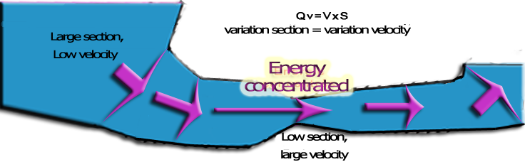
The evolution of sections, shows large sections with low losses and a "precious" technical area where the energy is concentrated, so as to reduce the precious organs , despite the head losses that involve high speeds. Changes sections and directions are progressive.Minimize pressure losses and focus energy are two rules that lead to a respective increase and decrease of the dimensions. This opposition involves compromise between construction cost and performance. The compromise will be found based on the amortization period and the power of installation.
2: Capture energy:
Known parameters are the gross height (meters) and volume flow (m3 / h). We have seen that flow through our turbine includes axial component (parallel to the axis of the turbine) and a tangential component (rotation, swirl around the axis of the turbine)..
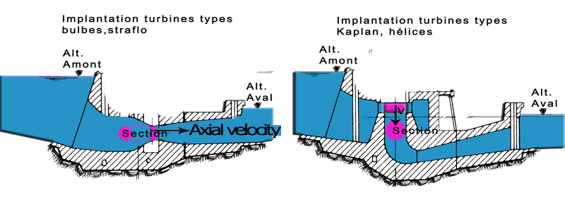
Let us begin by studying a turbine considering only the axial velocity.
Flow rate (m3 / h) given, the section (m²) swept by the propeller will give us axial velocity ( m/sec). The section swept by the propeller is a ring whose external diameter is the diameter of the helix, and whose inner diameter is the diameter of the hub:
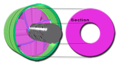
We will control the axial velocity, by choosing a radius of blade root and blade tip radius, determining the swept section. Recall that the kinetic energy of the axial velocity may be only 60% recovered, so we better advised not to over produce it, so that the proportion of tangential velocity is maximum. We try to create a maximum swept section, the limit will be the cost and size of the system.
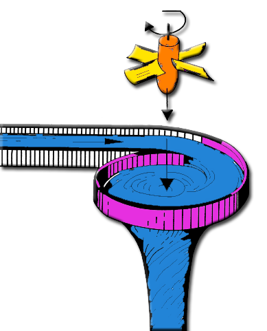
To transform the "axial" kinetic energy (relative to the axial velocity) , to couple on the propeller shaft, we will use our turbine blades like airplane wings , which through their lift force will generate torque.The lift causes the rotating blade for generating a torque on the shaft.(Video Software Heliciel)
The lift is a force perpendicular to the velocity seen by the blade. If we are positioned on a blade, the axial velocity, combined with the speed of rotation of the turbine, produces a resulting velocity perceived by the blade, which angle increases with the rotation speed. to almost zero rotation speed, the lift provides maximum torque because it is correctly oriented, but a lot of fluid passes through the turbine without transferring energy to the blade. at high rotational speed, the lift has an angle, generates less torque, but the amount of fluid passing through the propeller without exchanging energy decreases.There is therefore an optimum rotation speed which combines the direction of the forces of lift (and drag) optimally...We will not detail more here this principle (for more on this turbine operation), But we will retain the axial fluid stream generates a torque on the turbine shaft, with the lift of the blades.
In this video, fluid enters the turbine with axial velocity without any tangential component of rotation around the axis.
By reaction principle, the torque generated on the shaft, generates a rotation of the fluid in the opposite direction to the speed of rotation.This is the "induced tangential" velocity generated by the capture of the axial flow.
Considering the speed of the fluid, such as an amount of energy, we can say that any movement out of our turbine shows the energy that escapes us. The rotation of the fluid (tangential velocity) generated by the reaction torque of the turbine is energy lost. This energy would be captured, if at the output of the propeller no tangential velocity was seen..
So far we have considered only the axial flow generated by the flow, it is time to attend to the tangential velocity, that the guide vanes can generate, using load height, et voir comment nous allons capter cette vitesse tangentielle introduite en entrée de turbine.
We have seen that our propeller generates a tangential velocity induced by transforming the axial velocity , to torque on the propeller shaft .This induced tangential velocity is opposite to the rotational direction of the propeller shaft. Any output speed is a loss, if we enter into the turbine, a tangential velocity equal and opposite to the induced tangential velocity at the output propeller,the sum of two opposing tangential velocities will give a zero output tangential speed. We could say that we have captured all the tangential kinetic energy!!
|
|
- The tangential velocity produced by the guide vanes and the tangential velocity induced by the turbine cancel each.
- The heights load consumed by the crossing of the turbine, the guide vanes and the head losses of the entire system, are adapted to the gross head of site.
- Summary of the method we will use in: tutorial example design of a small hydroelectric power plant:
Input data used:
- Heliciel (design and calculation of the turbine)
- Mecaflux (calculation of head losses and speeds according Bernoulli)
- Spreadsheet (curve plot showing the operating point)
results output
- Load height (meters) (difference between the upstream and the downstream basin area) = 4.3 meters
- Volumetric flow of the site (m3/sec) = 12 m3/sec
- Blade tip radius = 1000 mm
- Radius at the blade root = 600 mm (60%)
- width (chord) at the blade root = 738 mm
- width (chord) at the blade tip = 1138 mm
- number of blades = 4
Design phases:
- Crossing speed of the turbine and the operating point
- Optimal rotational speed
- Tangential velocities to introduce with the guide vanes
- Assessment of depression generated by darft tube
- Total shaft power, in the event that the guide vanes introduced the tangential velocity calculated
- 3D model and definition of twisting, the IGS format for the creation of the blade
- A: Determining the operating point of the system (finding the the velocity of the fluid passing through turbine)
- Defining the geometry of the turbine:
- Use héliciel to enter your geometric data (diameter at root and tip of the blade, width foot and blade tip)
- Noted pressure deltas generated by the turbine to the optimum rotation speed, according to a range of fluid flow::
- Héliciel used to calculate the delta pressure, following a series of fluid flow rates, seeking optimum rotation speed. Take deltas pressure versus flow tested (convert pressure in meters)
- Note the head losses through the system, using the same flow range::
- Mecaflux use to create a curve of head losses, according to the flow range
- Plot the height "necessary" according to a range of speeds through the system, at the section of the turbine (swept area):
- create a curve, height "necessary", by subtracting from the gross height, the sum of the delta pressure (pressure losses and delta pressure turbine)identified in Phase 2 and 3. (Deltas pressure must be converted to meters) The height "necessary" will be placed on the y-axis. The flow rates will be converted into speed by dividing the flow rate (m3 / s) by the swept area section(m²) . Speeds obtained will be placed on the x-axis.
- Operating speed (giving the flow rate of operation) is given, where the curve height necessary, reaches the value of the height of the gross head of site.
- Defining the geometry of the turbine:
- B: Collection and interpretation of results at the operating point found:
- optimum rotation speed:
- In Heliciel, enter the fluid velocity found and launch the search for optimum rotation speed to update the turbine and its performance
- tangential velocities, to introduce with the distributor:
- In héliciel identify tangential velocities (average) for calculating of average inclination angle of the vanes of guide vanes.
- Calculation of the total power to the shaft, in the case where the guide vanes, introduced a tangential velocity opposite to that induced by the turbine:
- In Heliciel software, note the tangential speed at the blade tip, in the fluid velocities results area (in radians / sec) (let your mouse a few moments on the chart to display the bubble info) and enter this tangential velocity (average) in the menu "Settings / Insert a tangential flow upstream". Restart the search optimum rotation speed to update the propeller and its performance
- Assessment of depression, and draft tube sections, and evaluation gain power generated by draft tube:
- Calculate the average axial velocity of the propeller at the output by using the values of each element in the area of speed results HELICIEL.Calculate flow turbine output by multiplying the axial average speed calculated by the turbines section. Using the Bernoulli application (tool menu mecaflux):
- Check the pressure P1, as a result, and enter the desired speed in point 1(average axial velocity at the outlet of the turbine),
- the height at point 1 will be considered null and equal in point 2..
- The pressure at point 2 is the atmospheric pressure (enter 100000 pascals).
- The parameter that you will act to create a depression is the velocity at point 2. This speed is calculated using the flow rate at the turbine outlet, and the outlet section of the draft tube: Output speed = flow (m3 / s) / output section (m²). Depression in point 1 will be important if the output speed is low. not to expand too quickly (about 6 degrees angle max otherwise the head losses reduce the suction effect).the draft tube is limited by its size and cost, But also by the cavitation caused by excessive depression at the outlet region of the turbine. It will ensure that the depression in the blades, combined with depression of draft tube, do not drop the ambient pressure below the saturation vapor pressure.
- Enter the value of the depression caused by the draft tube in the "parametres" menu Heliciel software and restart the search for optimum rotation speed to update the propeller and its performance
- Calculate the average axial velocity of the propeller at the output by using the values of each element in the area of speed results HELICIEL.Calculate flow turbine output by multiplying the axial average speed calculated by the turbines section. Using the Bernoulli application (tool menu mecaflux):
- optimum rotation speed:
- C: Feasibility and adaptation of the turbine:
- The pressure at the turbine outlet: (gross Head- (elevation between the turbine outlet and downstream basin)) - ( turbine depression + draft tube depression+head losses) Must remain above the saturated vapor pressure.
- D: If phase C forces you to modify certain parametres,(Pipe diameters, radius of curvature of the elbows changes in sections estimated in the initial hypothesis), return to Phase A (have a coffee and take a rest merited) ,otherwise edit the igs file for manufacturing and record Heliciel parameters (save the project to the operating point found)
hydropower turbine propeller:
- Part 1: Parameters and operating parts of a turbine system.
- Part 2: The relation stator guide vanes and propeller
- Part 3: The design method of hydraulic turbine
- Part 4: Tutorial designing a turbine system.
- Tutorial hydroelectric turbine design 1/3 :Site power and turbine design
- Tutorial hydroelectric turbine design 2/3 :Design :guide vanes or stator
- Tutorial hydroelectric turbine design 3/3 :Choice sections, design draft tube
 Global site map
 Mecaflux
 Tutorials Mecaflux Pro3D
 Tutorials Heliciel
 Mecaflux Store
 Quotes, Orders, Payment Methods
 project technical studies