
Modeling a wing mast sail in heliciel
Introducing the mecaflux software suite:
Wings or foils modeling in heliciel
Aerial propeller modeling in heliciel
Boat propeller modeling in heliciel
Ventilation propeller modeling in heliciel
Wind turbine propeller modeling in heliciel
Tidal turbine modeling in heliciel
Kaplan propeller modeling in heliciel
Hydrofoil wings and sails
| drag and lift | wing or blade elements | losses at the wing or blade tips |
Understand and master design of Hydrofoil wings and sails:
The objective here is to remember the basics needed to construction of a wing a hydrofoil or a propeller.(propeller can be considered as a rotary wing).We will not make, for the moment, any difference between a wing and a foil because, apart cavitation , the methode is the same.Understand what is happening on the wing and flying, has took few centuries to humanity...and it will take some time to do it with less energy than birds.Move an anvil on 10 meters with a 10 megaton firecracker is impressive but a little expensive.
.
.
- The lift (newtons)) is the gentle force perpendicular to the fluid stream that carries the wing that generates the thrust of the propeller. The lift is good!
- The Drag (newtons) is the nasty forces pulls the wing in the direction of fluid flow, which prevents the wing to move, the propeller to rotate. The drag is not good! This is the drag that must be compensated by providing energy to the propeller shaft to rotate.
The tests in wind tunnels or pools (numerical or experimental) give us performance coefficients (no units) that will be the the basic data for the calculation of the forces on the wings propeller blades and foils:
- The Cd = drag coefficient and
- The CL= lift coefficient of profiles.
- The lift/drag ratio gives us the quality of the profile, a high finesse can lift a heavy load with little energy..Heliciel apply by default the best lift/drag ratio angles to the blade and wings.
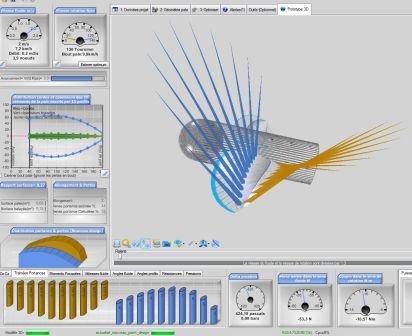
The drag and lift of a propeller in the software HELICIELObserve that the drag forces and lift increases with the square of the speed.
- The formula for the lift: Lift(2D)(en Newtons)=
CL X Wing area(m²) X Fluid density(Kg/m3) X ( fluid velocity²(m/sec) / 2).- for the drag is the same but with the CD:Drag(2D)(en Newtons)=
CD X Wing area(m²) X Fluid density(Kg/m3) X ( fluid velocity²(m/sec)/2)
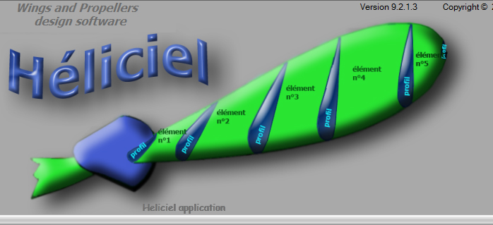
A wing could very well be defined by a single profile of constant width, but to answer the constraints of mechanical resistance and to obtain optimum performance, the actual shapes are generally more complex. To analyze and understand what is happening on a wing or propeller blade , it is convenient to cut it into slices, starting from the base to the tip, the shape of the sections are the profiles.The profiles describe the sectional forms of our blade. A portion flanked by two profiles is un an element of the blade or wing.
the elements and profiles of the blade
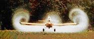
Lift resulting from the difference in pressure between the top and bottom of the wing. But the pressure differential generates leaks , because more fluid wants to get to the other side by the shortest path it finds! The shortest path is the tip of the wing or blade..

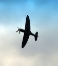
- The more is the lift near the wing tip, the more are the leaks. If the lift is distributed as far from the wing tip as possible ,this will limit leakage. This is great. The wing shape which distributed lift theoretically farthest from the end is the ellipse. Some aircraft have therefore simply adopted elliptical wings. the spitfire and elliptical wings focusing lift as far as possible from wing tip to prevent leakage. In practice, a trapezoidal shape is sufficient to get an effect similar to the optimum:
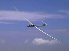
- More the blade or wing is short there are more leaks. We have therefore interest to distribute the surface on a large length and small width. The concept of Aspect Ratio helps us to evaluate this distribution:
- For a rectangular wing Aspect ratio = span (wing length)/ chord (width of the wing):
- Aspect ratio(all forms of wing)= span (wing length)²/(wing area)
A high aspect ratio is a lift distributed on a large surface therefore a difference of pressure between lower and upper surfaces not giving too much to the fluid the desire to get to the other sideCalculate the performance of a wing considering tip vortices and tip losses requires knowing the impact these vortices on the profiles 2D performance. This can be done by calculating the deviation of the fluid induced by the vortices. Calculating the speeds induced by the vortices, we can correct angles perceived by profiles and infer the performance of the wing of finite span (3D).The calculations of these speeds is achieved by the induced vortex theory that describes the relation between the lift and the vortices. To learn more:Theory wing of finite span based on the method of distribution of vortices.
Example of the influence of the shape and aspect ratio: vortices and wingtip loss of 4 wings of shapes and different aspect ratio, shown schematically in software Heliciel
Rectangular wing length of 2 meters Aspect ratio = 4 ratio (Lift / Drag) =16 |
Rectangular wing length of 9 meters Aspect ratio = 18 ratio (Lift / Drag) =32 |
| Triangular wing length of 2 meters. Aspect ratio = 5 ratio (Lift / Drag) =19. | Triangular wing length of 9 meters. Aspect ratio = 33 ratio (Lift / Drag) =36 |
A device reduces the blade tip leakage by placing a barrier:
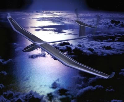
- The Solar Impulse project aims to take off and fly autonomously, day and night, an airplane powered only by solar energy, to perform round the world without fuel or pollution ..
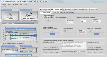
In the tab dimensions blade or wing a series of sliders allows to model the shape of your blade or wing in all its dimensions..
We now turn to a specific phenomenon hydrofoils and marine propellers: Cavitation
If you wish to learn more:
 Global site map
 Mecaflux
 Tutorials Mecaflux Pro3D
 Tutorials Heliciel
 Mecaflux Store
 Quotes, Orders, Payment Methods
 project technical studies