
Aircraft propeller design tutorial with Heliciel (1/2)
Designing an aircraft propeller with Heliciel means gathering a few data (flight speed, engine rpm, blade length, engine cowl size, drag, torque), entering them in the project tabs, then reading the thrust and shaft power. In this tutorial's example, a scale model flies at 34 m/s with a drag of 30 N. Our propeller, with a 140 mm radius, gives 22 N at 8,000 rpm, then 33 N at 10,000 rpm.
Heliciel builds the geometry of the aircraft propeller and analyses its performance. It lets you edit a blade plan, made of its profiles with their pitch angles. It also produces a 3D model, and prototyping is possible thanks to the blade IGS (IGES) file, readable by numerically controlled machines and other rapid prototyping machines. This preliminary-design propeller must of course be tested and evaluated on models or test benches, without endangering the safety of persons.
On this page:
- The data to gather before designing the aircraft propeller
- Entering the project data: fluid, goal, operating point
- Propeller blade dimensions: length, chords, thickness
- Building the blade twist
- Reading thrust, torque and shaft power
- Raising the rpm to reach the required thrust
1: The data to gather before designing the aircraft propeller
Let's start by opening an aircraft propeller model in Heliciel.
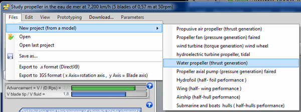
The File > New project (start from a model) menu offers, among others, the propulsive air propeller (thrust generation).
The data to gather before building our propeller are listed below. We took a scale model as the example.
- Estimated flight speed: about 120 km/h, or 34 m/s.
- Engine rotation speed: 8,000 revolutions per minute, the rpm that gives the best efficiency. Your engine runs at its best speed, is economical with fuel and suffers no premature wear.
- Maximum blade length the aircraft can have without hindering landing: 140 mm. The largest propeller is the one with the best efficiency, provided the blade tip speed stays below transonic speeds (about 0.7 times the speed of sound, which, with the 331 m/s the Fluid tab shows for air, is about 230 m/s or 830 km/h). Beyond that, aerodynamic performance degrades and the propeller loses efficiency. Here, at 8,000 rpm, the blade tip moves at 117 m/s (422 km/h): we stay far from that limit.
- Engine cowl size: 75 mm. It determines the radius at the blade root: there is no point in shaping the blades in front of the cowl (unless you want to cool the engine).
- Resistance to forward motion (drag, in newtons) estimated at this speed: 30 N. The drag of the wings and ailerons can be studied with Heliciel in a wing project. The drag of geometric shapes can be evaluated with Mecaflux. The sum of the drags at the given speed is the thrust the propeller must provide at that speed.
- Engine torque at this rotation speed: 1.9 N.m.
- An engine torque curve against rpm lets you check that the torque the propeller demands, as a function of its rotation speed, always stays below the engine curve.
2: Entering the project data: fluid, goal, operating point
Let's enter the "Project data", in tab 1: Project data.
- Tab 1.1 Fluid: click "Modify the ambient fluid", select air at 20 degrees and choose an altitude of 0 metres (click "Yes" at the proposed choice).
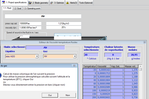
You should get these fluid parameters:
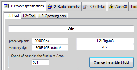
- Tab 1.2 Goal: leave "Propulsive propeller".
- Tab 1.3 Operating point:
- fluid speed: enter 34 m/s;
- rotation speed = engine rpm, preferred: enter 8,000 revolutions per minute.
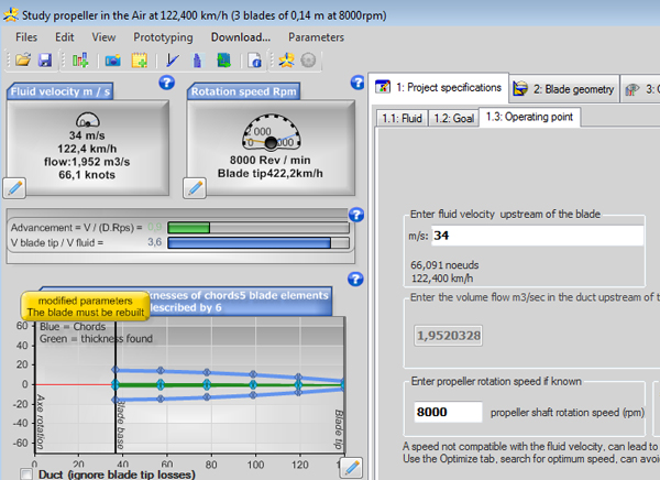
The two dials on the left repeat the operating point: 34 m/s (122.4 km/h) and 8,000 rpm. The title bar shows that this model has 7 blades of 0.9 m before we modify it.
3: Propeller blade dimensions: length, chords, thickness
Under tab 2 "Blade geometry", we enter the dimensions of the blades of the propeller we want to build, in tab 2.1 Blade dimensions.
Blade length
- Radius at the blade tip = 140 mm.
- Blade root: we set the radius at the blade root, the zone where the blade starts to be effectively shaped, to 26% of the radius, or 36.4 mm. It thus starts at about the level of the engine cowl (75 mm of overall size divided by 2 gives the approximate blade root radius).

Blade width (chord)
- Chord at the blade root: let's enter 30 mm.
- Chord at the blade tip: a tapered blade ending with a chord of 8 mm.
- Intermediate chords: in this example we choose a linear distribution. We therefore click "Linearize" and do not use the slider that modifies the distributions.
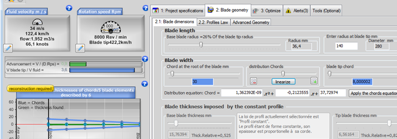
Warning: each time you change a chord, you must update the chord distribution by clicking "Linearize". You can then modify this distribution with the slider. If you want to keep a distribution, note its equation: you can then apply it in a later setting.
Blade thickness
The blade thickness will not be entered, because we chose the "constant profile law" in tab 2.2, with the NACA 1408 profile loaded with the default propeller project. The blade widths (chords) therefore also determine the blade thickness, since the relative thickness is fixed with respect to the chord (here 0.080 times the chord, or 8%).
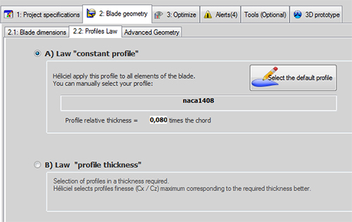
We could have set the number of blades, but we will look at it when we optimize our propeller.
4: Building the blade twist
All that remains is to start building our blade (click  ) and test its performance. This function builds the twist of the blade, optimized for the operating point described by the rotation speed and the fluid speed.
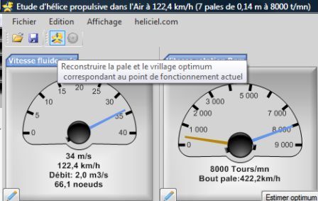
The button's tooltip sums up its role: rebuild the blade and the optimum twist matching the current operating point.
The twist is not entered: Heliciel calculates it for the operating point you impose (fluid speed and rotation speed) and for the chords you chose. If you change one of these settings, rebuild the blade so that the twist and pitch angle of the profiles follow.
The results pane shows the performance of our propeller, and the 3D model tab is updated.
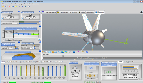
After the rebuild, the Prototype 3D tab shows the twisted blade, and the performance results appear at the bottom of the window. The prototype has 7 blades here.
5: Reading thrust, torque and shaft power
Looking more closely at the performance, we check whether the thrust and power match the needs of our aircraft.
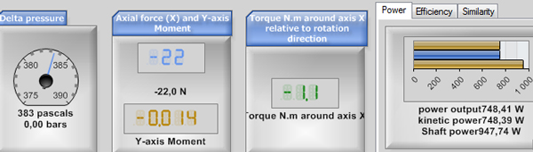
Performance at 8,000 rpm: axial force of 22.0 N in absolute value (the display carries a minus sign, which depends on the reference frame), torque of about 1.1 N.m, useful power 748 W and shaft power 947.74 W.
At 120 km/h, we estimated that the aircraft has a drag of 30 newtons. We read on the engine curve that the torque at 8,000 rpm was 1.9 N.m. Power is calculated as follows:
- power (kW) = torque (N.m) × rotation speed (rpm) / 9,550.
With this formula, we know that the engine power at 8,000 rpm is (1.9 × 8,000) / 9,550 = 1.59 kW, or about 1,590 watts.
Our propeller delivers a thrust of about 22 newtons, with a torque of 1.1 newton-metres and a shaft power of about 947 watts. Thrust multiplied by speed (22 N × 34 m/s, or 748 W) gives the useful power. The propeller's efficiency is therefore 748 / 947.7, or about 0.79.
The calculated thrust (22 newtons) is lower than the estimated drag (30 newtons): we can estimate that the aircraft will not reach the required speed. As we have some power margin, the engine power (1,590 watts) being higher than the shaft power (947 watts), we can try to raise the rpm to increase thrust.
6: Raising the rpm to reach the required thrust
Let's go to 10,000 rpm.
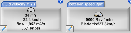
We rebuild our blade and its twist (click ) so that it matches this new operating point, and we update the performance. We get a new thrust of about 33 newtons (32.6 N on screen) at 10,000 rpm.
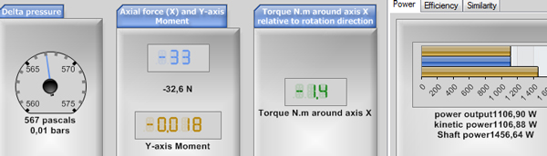
Performance at 10,000 rpm: axial force of 32.6 N in absolute value, torque of 1.4 N.m, useful power 1,107 W and shaft power 1,456.64 W.
This thrust exceeds the 30 N drag. We note that the power demanded from the shaft has risen to 1,456 W, and that the load torque on the propeller shaft is now 1.4 N.m. You will need to check on the engine curve that it does supply this torque at 10,000 rpm.
- These 11 extra newtons of thrust cost us 509 W (1,456 W minus 947 W).
The propeller's efficiency drops a little: 1,107 / 1,456.6, or about 0.76. We chose the power route to increase thrust. In these energy-saving times, we might perhaps have tried to optimize our propeller instead!
To go further, we can see how to optimize our aircraft propeller in the second part of the tutorial: rpm, diameter and number of blades.
 Global site map
 Mecaflux
 Tutorials Mecaflux Pro3D
 Tutorials Heliciel
 Tutorials Heliciel PRO CFD
 Mecaflux Store
 Compare software functions
 Quotes, Orders, Payment Methods
 project technical studies