
Optimizing an Aircraft Propeller (Tutorial 2/2): Profile, Number of Blades and Chords
← Part 1: designing an aircraft propeller · Part 2: optimizing the propeller
To optimize an aircraft propeller, we act on three levers, the blade profile, the number of blades and the chord distribution, until we get the thrust we want with the torque the engine can supply at its speed. This second part of the aircraft propeller design tutorial shows, result after result, how each lever changes the thrust and the torque in Heliciel.
On this page:
- The imposed data and the optimization levers
- First lever: a more cambered profile, the naca6412
- Second lever: reducing the number of blades
- Third lever: the chord distribution
- Summary and possible next step
1: The imposed data and the optimization levers of an aircraft propeller
Part 1 gave us the following data:
- the optimum rotational speed of our engine: 8,000 rpm. It is the speed that gives the most power for the least energy, the speed for which the engine was designed;
- the torque of our engine at this speed: 1.9 N.m;
- the speed of our aircraft in cruise flight: 120 km/h, or 34 m/s;
- the drag of our aircraft: 30 newtons;
- the maximum blade length of our propeller: 140 mm.
The parameters available to optimize the propeller are:
- the number of blades (we can reread this reminder on optimizing the number of blades);
- the chord distribution (with this reminder on the chord of profiles and chord distribution);
- the shape of the profiles (with this reminder on choosing blade profiles).
At the imposed rotational speed (8,000 rpm) and with 7 blades, we had obtained, in part 1, a thrust that was a little low: 22 N, instead of the 30 N needed to offset the drag.
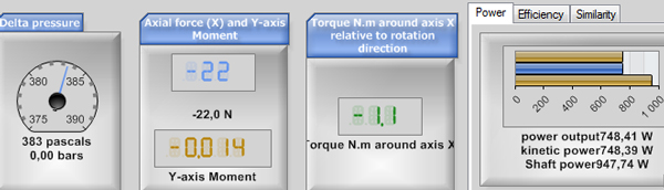
The performance displays for 7 blades with the naca1408: axial force -22 N, torque 1.1 N.m, output power 748 W for 948 W at the shaft.
2: Raising the thrust with a more cambered profile
To raise the thrust without raising the rotational speed, we can use what we saw on the shape of profiles: increasing the camber of the profile. Under the 2.2: Profiles Law tab, we see that the profile used for our blade is the naca1408.
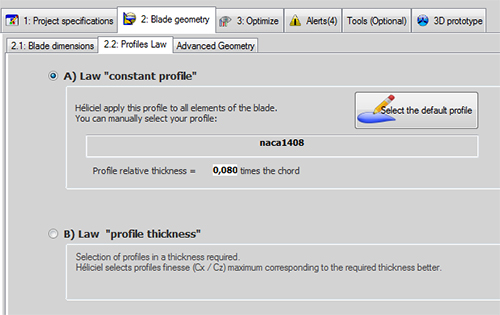
Tab 2.2: Profiles Law. The naca1408 is applied to the whole blade.
By clicking Select the default profile, the profile database is displayed. Under the database tab, we can sort the grid by clicking a column header. The cz_fmax header gives the lift coefficient of profiles at maximum lift-to-drag ratio: one click on this title ranks the profiles by this coefficient.
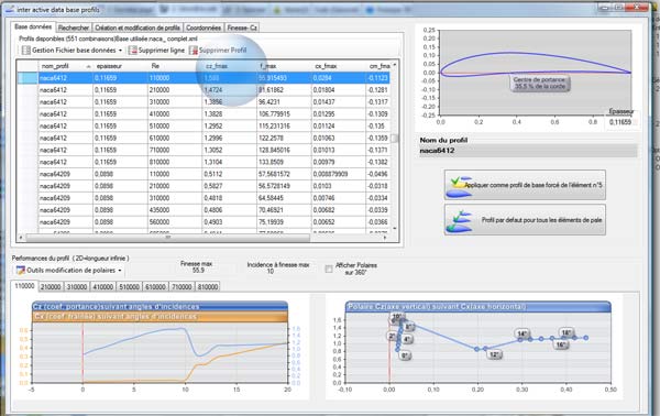
The database sorted by cz_fmax, with the naca6412 selected. On the right, its cambered drawing; at the bottom, the polars for each Reynolds number.
In this database, we choose the profile that offers the best Cl (lift coefficient): the naca6412. Note in passing that its camber is more pronounced than that of the naca1408 we were using.
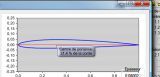
The naca1408, our starting profile, much less cambered.
To apply this new profile to the propeller, we click Default profile (profile law).
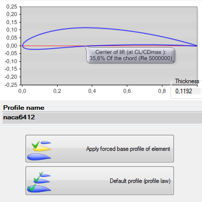
The naca6412 (centre of lift at 35.6% of the chord) and the two application buttons: one forced element, or the default profile.
We then click Rebuild the twist at the operating point:  . The propeller performance is displayed. Let us not forget to set the rotational speed back to 8,000 rpm.
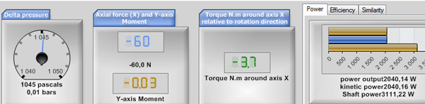
With the naca6412 and 7 blades: axial force -60 N, torque 3.7 N.m, shaft power 3,111 W.
The thrust (60 N) has indeed risen thanks to the higher lift, but so has the torque: 3.7 N.m, when we have only 1.9 N.m. To lower the torque without changing the rotational speed, we could go back to the database and look for a profile with a lower Cd, since the drag coefficient is largely responsible for the torque, as we looked for a higher Cl. But this is a tutorial: we choose to reduce the number of blades, to explore other levers.
3: Reducing the number of blades of the aircraft propeller
Since the thrust is greater than what we need, let us remove a few blades. With 7 blades, that is perhaps a little many, and at the price of blades, it will save money. Under the 3: Optimize tab, we change the number of blades.
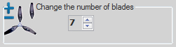
The "Change the number of blades" setting of the Optimize tab (here 7 blades).
We go to 5 blades and rebuild:
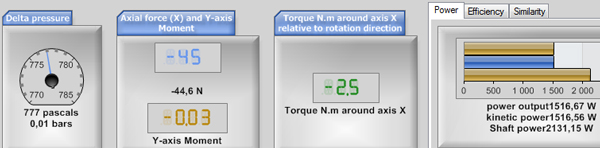
With 5 blades: axial force -44.6 N, torque 2.5 N.m, shaft power 2,131 W.
The thrust is down to 45 N and the torque to 2.5 N.m. They have dropped, but not enough for our target of 30 N for 1.9 N.m. We therefore go to 3 blades and rebuild:
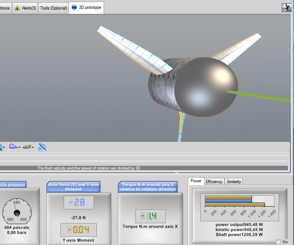
The 3-blade propeller in the 3D prototype, with its displays: axial force -27.8 N, torque 1.4 N.m, shaft power 1,208 W.
The torque falls below 1.9 N.m, but the thrust is only 28 N. One more blade? No, that costs too much, and we have understood how the number of blades changes our performance. Let us try another lever.
4: Changing the chord distribution of the blade
We change the blade geometry a little. To raise the thrust, we slightly increase the blade area by changing the chord distribution of the profiles: we drag the distribution Chords slider until it shows "Add 0.0400x Chord el:2".
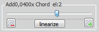
This slider drives the chord distribution equation. It is sensitive: if we cannot reach this value, we click linearize to start again from a linear chord, then we repeat the operation.

This new chord distribution swells the blade a little:

The chart of chords (blue) and thicknesses (green) after the change, for our 140 mm blade (cropped view).
We rebuild:
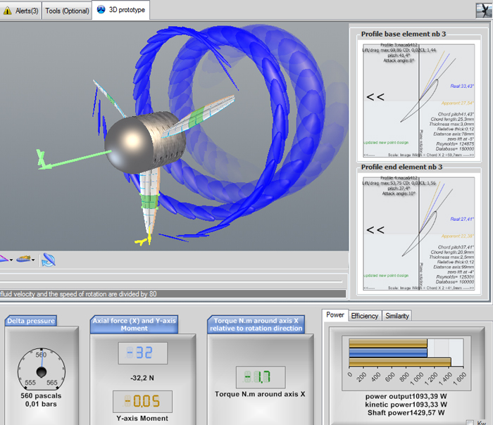
The 3-blade propeller with shaped chords, at 34 m/s and 8,000 rpm: axial force -32.2 N, torque 1.7 N.m, output power 1,093 W for 1,430 W at the shaft.
The thrust is now 32 N, with a torque of 1.7 N.m. This propeller is therefore made to measure for our design brief.
5: Summary and possible next step to optimize the blade
We have seen how to adapt the propeller to the imposed operating conditions. In terms of propulsive efficiency, however, it offers only 0.76 (1,093 W of useful power for 1,430 W at the shaft). Work on the profile may win us a little efficiency.
The parameters for optimizing a propeller are many. There is no miracle recipe, because design briefs are as varied as the goals pursued. Heliciel gathers the functions that quickly test the optimization hypotheses we want to follow, but the choice of compromises is endless and stays in your hands.
To go further, we can plot the performance curves of the propeller with the multiple analysis, a curve-editing tool that lets us test the propeller, or go back to part 1 of the aircraft propeller tutorial.
 Global site map
 Mecaflux
 Tutorials Mecaflux Pro3D
 Tutorials Heliciel
 Tutorials Heliciel PRO CFD
 Mecaflux Store
 Compare software functions
 Quotes, Orders, Payment Methods
 project technical studies