
Wind turbine propeller modeling in heliciel
Wind turbine generator: types and operation (dynamo, alternator, induction)
A wind turbine generator is the electrical machine that turns the rotation of the rotor into electric current. There are three families: the dynamo (direct current), the alternator or synchronous generator, and the asynchronous (induction) generator. They differ in robustness, maintenance, rotational speed and the way they connect to the grid or to batteries.
The rotor drives the machine either directly or through a gearbox. Either way, for a given wind energy resource, the generator delivers a power that depends on its rotational speed. That curve is the one we will later try to match with the curve of the wind turbine, as explained on the page about building a wind turbine.
In this page:
- Types of wind turbine generators and the principle of induction
- The DC generator (dynamo)
- The alternator: synchronous AC generator
- The asynchronous generator
- Dynamo or alternator: advantages and drawbacks
- Connecting a wind turbine to the grid: fixed or variable speed
- Example of making an axial flux generator with permanent magnets
1: Types of wind turbine generators and the principle of induction
The wind motor, meaning the rotor and its shaft, can drive three types of electric generator:
- a DC generator (dynamo);
- a synchronous AC generator (alternator);
- an asynchronous AC generator (induction generator).
Each one turns mechanical rotational energy into electrical energy, minus the losses in the generator. The mechanical energy the rotor captures depends on the wind, so the electrical output also depends on the efficiency of the machine.
The phenomenon at work is induction. A conductor moving in a magnetic field develops a voltage across its ends, and a current if it is connected to a load. The same happens if the conductor stays still and the field varies. All generators rely on this principle. They have two main parts: one that creates the magnetic field, the field system (inductor), and one where the useful voltage appears, the armature. In an alternator, the field system rotates with the rotor and the fixed armature forms the stator.
2: The DC generator (dynamo)
The dynamo has two parts:
- the magnetic circuit, with its magnetizing coil, whose purpose is to create the field in the air gap: this is the field system (inductor);
- the armature winding, where we collect the electrical energy produced when the wind motor turns the rotor.
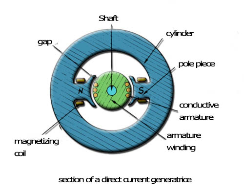
Cross-section of a dynamo: the magnetizing coil creates the field between pole pieces N and S, and the armature turns in the air gap.
To collect this energy, the armature carries a commutator. The one in the simplified dynamo below has two insulated 180° segments. Two brushes, placed face to face, touch segment A and then segment B in turn. The current therefore always keeps the same direction in the load.
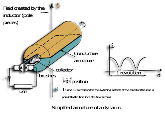
Simplified dynamo armature. The curve on the right shows the current over one revolution: it keeps its direction but drops to zero at the commutation instants t1 and t2, when the loop is parallel to the field lines.
A real machine has a large number of segments, matching a large number of conductors. The job stays the same: to pass a current of the same direction through all the strands located under a pole.
If the flux created by the magnetizing coil is constant (compensated machine), the electromotive force E is proportional to the rotational frequency. The voltage u across the machine and the current i it delivers are related by:
u = E − R × i
where E is the electromotive force (V), R the armature resistance (Ω) and i the current delivered to the load (A).
3: The alternator, a synchronous AC generator
A synchronous generator produces a current whose frequency is tied to the rotational speed. To feed a grid directly, it must therefore turn at a constant speed, which sets the grid frequency. The machine has two parts:
- the field system (inductor), which creates the magnetic field in the air gap, is mobile here: this is the rotor, driven by the wind motor. It is either a wound rotor fed through two slip rings, where the current always flows in the same direction, or a permanent magnet rotor, which removes brushes and slip rings, common sources of failure;
- the armature, where we collect the energy, is fixed to the casing and connected to the load: this is the stator. It can be single-phase or three-phase. Three-phase gives an almost sinusoidal AC voltage, hence a better efficiency.
With a wound rotor, the excitation current comes from an independent source (storage battery, small dynamo): the machine is said to have separate excitation. With permanent magnets, excitation is free and needs no maintenance.
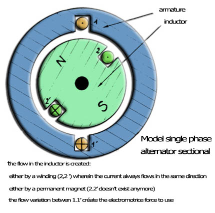
Single-phase alternator in cross-section. The field flux comes from a winding carrying a current of constant direction, or from a permanent magnet; its variation through the armature creates the useful electromotive force.
4: The asynchronous generator
The asynchronous generator combines simplicity, robustness and low cost. Its rotor usually consists of two rings joined by bars, like a squirrel cage wheel. The grid feeds the stator with three-phase current, which produces a rotating magnetic field. When the rotor turns, an induced current appears in the bars and creates another magnetic field.
The machine only delivers current to the grid when its rotor turns slightly faster than synchronous speed, by about 1% to 2%. It needs reactive current (90° out of phase) to maintain the stator magnetic field, and a bank of capacitors supplies it.
5: Dynamo or alternator: advantages and drawbacks
The dynamo. Its main drawback is the presence of brushes and a commutator, which must be checked periodically. It is also heavier and more expensive than an AC generator. In return, it needs no complex device to charge batteries: a simple diode, rated for the nominal current of the dynamo, prevents the battery from discharging into the armature when the machine is stopped.
The alternator. Especially with a permanent magnet field rotor, it has many advantages. It needs no maintenance, since it has no rubbing parts. For equal power, it is lighter and cheaper. On the other hand, it must turn faster and more steadily than the dynamo (generally 3,000 rpm) and it requires a rectifier to charge batteries. Despite these constraints, its use is general, except for low-power wind motors whose rotational speed is not stable enough. Three-phase permanent magnet alternators are the usual choice.
Note: a grid-connected wind turbine fitted with a synchronous generator must be interfaced with the grid by a rectifier-inverter set.
6: Connecting a wind turbine to the grid: fixed or variable speed
To convert wind energy into electrical energy, the generator, synchronous or asynchronous, can supply current directly to the grid. The turbine then runs at a fixed speed, or nearly so. To increase efficiency, its speed should rather vary with the wind. Three basic circuits make this possible, each relying on one or the other generator.
First circuit (figure 1). A synchronous generator feeds the grid through an inverter. The AC output of the generator is rectified to DC, then converted to AC at grid frequency (50 or 60 Hz). The generator no longer needs to run at a fixed speed, and the turbine captures more energy at low wind speeds. On the other hand, the added rectifier and inverter make this circuit expensive. The current produced is not always of good quality: it contains harmonics, a kind of parasitic ripple.
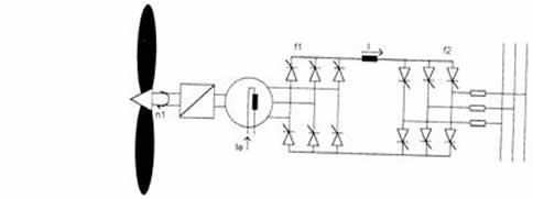
Figure 1: from the rotor to the grid, we read the gearbox, the generator with its excitation current, a first thyristor bridge that rectifies, an inductor, then a second bridge that converts the current back to three-phase AC for the grid.
Second circuit (figure 2). It relies on an asynchronous generator connected to the grid through thyristors mounted back to back, which the diagram shows on each phase. When the turbine reaches full power, a switch short-circuits these thyristors, which are not designed for high power. This circuit costs less than the previous one and the output current is of good quality. At low wind, however, total production drops: the switches commute frequently. To limit these commutations, the generator speed then stays below synchronous speed and the controller waits for the wind to rise again. Meanwhile, the generator may run as a motor and draw power from the grid.
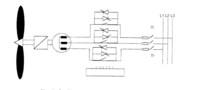
Figure 2: asynchronous generator, back-to-back thyristors on each of the three phases, switches and connection to grid lines L1, L2 and L3.
Third circuit (figure 3). This is the most representative of variable speed generators. It uses a synchronous generator. The current is not injected directly into the grid but into a converter, that is, all the electronics placed downstream (rectifier, inverter, filter). The converter adjusts the rotor speed to maximize efficiency, and the magnetization can always be controlled freely.
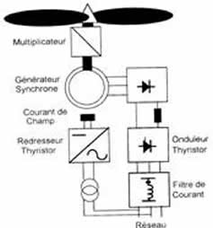
Figure 3: circuit of a variable speed generator. From top to bottom: the rotor, the gearbox, the synchronous generator with its field current, the rectifier, the inverter and the current filter before the grid.
By reducing the magnetic flux, we reduce core losses and winding losses. But at a certain specific power, this reduction lowers the voltage and leads to higher currents at the generator output, hence higher losses in the resistances. The two losses must therefore be balanced to keep maximum efficiency. Total losses can then be lower than for a fixed-speed synchronous generator.
Fixed-speed generators still dominate the market by far. Variable speed generators should be used more and more, even if the energy gain does not offset the cost of the electronics they require, because their decisive advantage is the low noise level of the wind turbines that go with them.
To go further, we can look at an example of making an axial flux generator with permanent magnets, see the whole approach in the article on how to build a wind turbine, or consult the bibliography on propellers, wings and wind turbines.
 Global site map
 Mecaflux
 Tutorials Mecaflux Pro3D
 Tutorials Heliciel
 Tutorials Heliciel PRO CFD
 Mecaflux Store
 Compare software functions
 Quotes, Orders, Payment Methods
 project technical studies