
Blade element momentum (BEM) theory: propulsion and traction propellers
Blade element momentum theory (BEM) for a propulsion propeller completes Froude theory, which gives the overall thrust of a propeller but ignores the blade shape: it computes the forces on a small slice of blade, links them to the induced velocities, then sums the slices to get the thrust and absorbed torque of the whole propeller. This page sets out the blade element equations for a propulsive propeller, coupled to the momentum balance.
In this page:
- Blade element theory: principle of the propeller calculation
- Forces on a blade element: thrust and torque
- Coupling with momentum and induced velocities
1: Blade element theory, principle of the propeller calculation
Froude's momentum theorem tells us the propulsion (or traction) force of a propeller, but not its design. This global method ignores the geometric and aerodynamic characteristics of the blade section (the airfoil). We can, however, take into account the forces acting on one blade element and integrate them over the propeller radius. This is blade element theory.
It makes visible the components of the induced velocity introduced in Froude's method, and establishes geometric relations between the velocity vectors reaching a blade element. It gives the torque absorbed by an element and the thrust it generates. Since it studies one element at a time, we sum the elements to obtain the total thrust and the absorbed torque of the propeller.
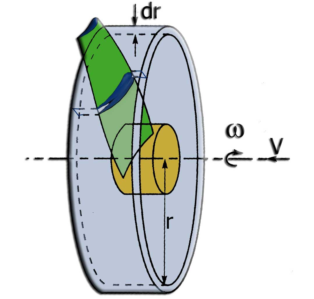
Figure 1: a rotor that turns and advances. A ring of width dr, at radius r, cuts one element out of each blade.
Figure 1 shows a rotor turning at angular speed Ω while advancing at speed V in the fluid. Figure 2 shows the section of a blade element of width dr, located at distance r from the rotor axis.
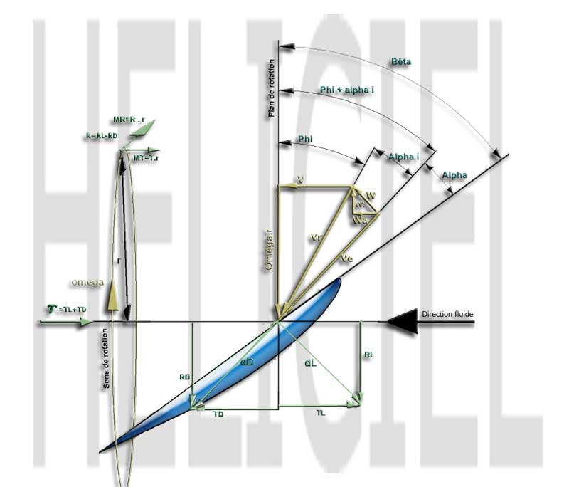
Figure 2: velocities, angles and forces on a propulsion propeller airfoil.
The figure shows that a blade element does not simply see the resultant of the forward speed and the rotation speed (the two combine as vectors: Vr = √(V² + (Ωr)²)). It sees an inlet velocity Ve, modified by the tangential induced velocity wt and the axial induced velocity wa. A sum of forces on the rotation plane and on the rotor axis then yields the equations of thrust and absorbed torque for an element of width dr.
2: Forces on a blade element, thrust and torque
The thrust dT and the torque dQ of the element are written:
![dT = dL cos (phi + alpha i) - dD sin (phi + alpha i) and dQ = r [dL sin (phi + alpha i) + dD cos (phi + alpha i)]](../../images%20formules/dt_dq.jpg)
Equations 1 and 2.
In these equations, dL and dD are the lift and drag forces on the airfoil. They are computed with the lift coefficient (Cl, Cz in French), the drag coefficient (Cd, Cx in French) and the chord c of the airfoil at the local radius r, for a ring of width dr (radius step between two annular elements):
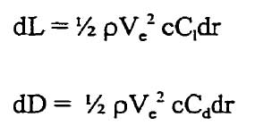
Equations 3 and 4.
The thrust equation of the blade element is used to evaluate the thrust developed by a circular ring of radius r and width dr carrying B blades. Combining equations 3 and 4 with equation 1, the thrust on the ring is:
![T ring = B 1/2 rho Ve squared c dr [Cl cos (phi + alpha i) - Cd sin (phi + alpha i)]](../../images%20formules/T_anneau.jpg)
3: Coupling with momentum and induced velocities
The momentum balance, with the acceleration wa given to the fluid in the disc, provides a second expression of the ring thrust:

Equating the ring thrusts given by these two expressions, we obtain:
![rho 2 pi r dr (wa + V) 2 wa = B 1/2 rho Ve squared c dr [...], hence 8 pi r (wa + V) wa = B Ve squared c [Cl cos (phi + alpha i) - Cd sin (phi + alpha i)]](../../images%20formules/eq00.jpg)
Equations 6 and 7.
with:
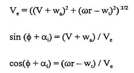
Equation 7 is the first of a system of two equations with two unknowns, wa and wt, used to solve for the velocities induced by the rotor blade. The torque equation provides the second. The system is solved by iterations, element by element, as for energy-capturing rotors: we start from an estimate of wa and wt, compute Ve and the angle φ + αi, read the airfoil's Cl and Cd for the corresponding angle of attack, then recompute wa and wt until they stop changing. The thrust and torque of the element follow, and their sum over all elements and all blades gives those of the propeller.
This page is an extract from Mr. Joncas's thesis.
The page on propeller induced velocity explains how Heliciel evaluates the induction of each blade element with this method, coupled to momentum.
To go further, we can review Froude theory for traction propellers, see the full version with corrections for energy-capturing rotors, or consult the bibliographic references.
 Global site map
 Mecaflux
 Tutorials Mecaflux Pro3D
 Tutorials Heliciel
 Tutorials Heliciel PRO CFD
 Mecaflux Store
 Compare software functions
 Quotes, Orders, Payment Methods
 project technical studies